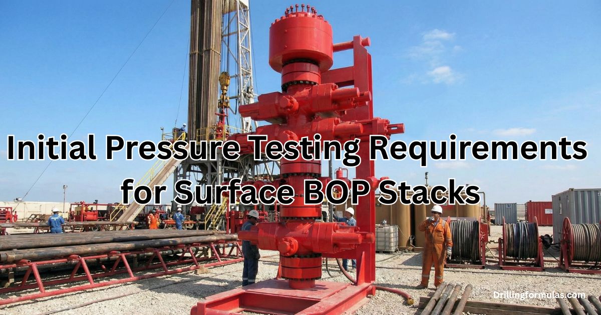
Why do we use High-Vis Sweep in drilling operation?

In oil and gas industry, a specialized drilling fluid known as high-vis sweep is often used and its primary purpose is to optimize hole cleaning and remove cuttings from the wellbore. What distinguishes this fluid is its heightened viscosity, a quality achieved by incorporating polymers or other additives into the base drilling fluid. This augmented viscosity empowers the sweep fluid to transport cuttings up the annulus out of the well.

Continue reading

What is a Back Pressure Valve (BPV)?

A Back Pressure Valve (BPV), also known as a tubing plug, serves as a one-way check valve typically placed within a specially machined profile in the tubing hanger or plug bushing. Its primary function is to impede the flow of fluids and gases through the hanger while permitting the pumping of fluid into the tubing string. These valves find application in various well operations such as removing the production tree, facilitating the initial nipple up of the Blowout Preventer (BOP) stack, installing the tree during the nippling down of the BOP stack, and handling heavy lifts over the wellhead.

The installation or removal of BPVs can be carried out with either the tree or BOP stack nipple up on the tubing head. Moreover, they can be installed with or without pressure on the tubing. If the BPV needs to be installed through the tree with pressure on the well, a lubricator is necessary. Wellhead manufacturers offer diverse designs for Back Pressure Valves, which depend on the size and make of the hanger and wellhead. It’s crucial to note that only personnel specifically trained by wellhead manufacturers should undertake the installation and removal of these valves.

There are typically two types of BPVs: type “B” and type “H,” illustrated in the diagram below. Both types fulfill the same function. The choice between type “B” and “H” depends on the tubing hanger models. Some hangers may be equipped with type “B,” while others may require type “H.” Therefore, wellhead manufacturers can provide guidance on which types of tubing hangers are suitable for specific models.


References

Cormack, D. (2007). An introduction to well control calculations for drilling operations. 1st ed. Texas: Springer.
Crumpton, H. (2010). Well Control for Completions and Interventions. 1st ed. Texas: Gulf Publishing.
Grace, R. (2003). Blowout and well control handbook [recurso electrónico]. 1st ed. Paises Bajos: Gulf Professional Pub.


What are HCR Valves?

An HCR valve, also recognized as a High Closing Ratio valve, is a specialized type of gate valve widely employed in well control systems, particularly within the blowout preventer (BOP) stack. Its purpose is to deliver a dependable and efficient method for managing wellbore pressure and averting uncontrolled fluid flow during drilling, completion, and production activities.

Distinguished by a remarkable closing ratio, which represents the ratio of fluid pressure upstream of the valve to the hydraulic pressure needed for closure, HCR valves excel in sealing against elevated wellbore pressures, even in the face of sudden pressure surges.

Typically featuring a double-acting design, HCR valves possess two hydraulic chambers that can be pressurized for both valve opening and closure. This dual-system redundancy ensures continued operability, even if one hydraulic system encounters a failure. Operating at a typical pressure of 1,500 psi, HCR valves are engineered with a rising stem design, offering enhanced control during operations. Unlike some valve designs, HCR valves do not incorporate back-seating allowance, emphasizing their commitment to reliable and secure fluid control.

Engineered to endure challenging wellbore conditions, such as high temperatures, corrosive fluids, and abrasive sand, HCR valves are crafted from robust materials like forged steel or stainless steel. Protective coatings are applied to resist corrosion, enhancing their durability.

As integral components of well control systems, HCR valves play a pivotal role in ensuring the safety of personnel and environmental protection during drilling and production operations. Their high closing ratio, redundant systems, and robust design collectively contribute to their reliability and effectiveness in managing wellbore pressure and preventing uncontrolled fluid flow.

References

Cormack, D. (2007). An introduction to well control calculations for drilling operations. 1st ed. Texas: Springer.
Crumpton, H. (2010). Well Control for Completions and Interventions. 1st ed. Texas: Gulf Publishing.
Grace, R. (2003). Blowout and well control handbook [recurso electrónico]. 1st ed. Paises Bajos: Gulf Professional Pub.

Understanding Factors Leading to Low Density Drilling Fluid and Potential Well Control Events

The density of drilling fluid plays a critical role in well control during both drilling and completion operations. This article aims to explore the various factors that can result in low-density drilling fluid, potentially leading to well control challenges.

Accidental Dilution and Fluid Addition

Maintaining the hydrostatic pressure necessary to balance or slightly exceed formation pressure requires constant monitoring and adjustment of drilling fluid density. Accidental dilution of drilling fluid with makeup water in surface pits or the addition of low-density formation fluids into the mud column can reduce fluid density, triggering a potential kick. Rigorous vigilance in monitoring mud pits is essential to ensure the required fluid density is consistently maintained.

Gas Cutting

Large volumes of gas in the returns can cause a drop in the average density and hydrostatic pressure of the drilling fluid. Notably, gas cutting often occurs in an overbalanced condition downhole. If a formation containing gas is drilled, the gas within drilled cuttings can expand as it moves up the annulus, leading to gas cutting at the surface. Detecting this is crucial, as a flowing well indicates a kick, necessitating immediate well shut-in and initiation of the proper kill procedure.

Oil or Saltwater Cutting

Invasions of oil or saltwater from drilled cuttings or swabbing can reduce the average mud column density, causing a drop in mud hydrostatic pressure. While the effect of these liquids on average density is less pronounced than gas, the impact on bottomhole pressure can be substantial. Liquids, being less compressible, result in uniform density reduction throughout the mud column.

Settling of Mud Weighting Materials

The settling of desirable solids or drilled cuttings in a mud can significantly reduce mud density, affecting hydrostatic pressure. Barite sag, more prevalent in highly deviated wells, requires a combination of sound mud design and operational practices for management.

Loss of Equivalent Circulating Density (ECD)

Shutting down pumps during drilling connection can lead to a reduction in dynamic bottomhole pressure, causing the loss of ECD. This loss can allow formation fluids to enter the wellbore, known as “connection gas.” Observation of connection gas is an indication that static mud overbalance is lost, necessitating a potential increase in mud weight.

Cementing Operations

Improper cement mixing, lost circulation, or casing float equipment failure can compromise cement density and reduce hydrostatic pressure, leading to well control issues.

Cement Slurry Transition

As cement transitions from a slurry to a solid state, there’s a temporary reduction in hydrostatic pressure due to self-supporting cement solids before the structure becomes impermeable. This can potentially lead to an influx.

Closely monitoring the well throughout all phases of drilling, completion, and cementing operations is imperative for preventing and mitigating well control events. Nurturing a proactive approach ensures the integrity and safety of the wellbore.

To prevent well control events caused by low drilling fluid density, it’s essential to:

  • Maintain strict pit discipline and monitor fluid properties regularly.
  • Use appropriate mud additives to prevent gas cutting and control fluid rheology.
  • Monitor for oil or saltwater invasions and address them promptly.
  • Implement proper mud design and operational practices to minimize barite sag.
  • Maintain pumps running during pipe connections to avoid ECD loss.
  • Exercise caution during cementing operations and closely monitor pressure changes.

References

Cormack, D. (2007). An introduction to well control calculations for drilling operations. 1st ed. Texas: Springer.
Crumpton, H. (2010). Well Control for Completions and Interventions. 1st ed. Texas: Gulf Publishing.
Grace, R. (2003). Blowout and well control handbook [recurso electrónico]. 1st ed. Paises Bajos: Gulf Professional Pub.