Buoyancy Factor is the factor that is used to compensate loss of weight due to immersion in drilling fluid and you can find more information from this article > buoyancy factor calculation . In that article, it demonstrates the buoyancy formula only for one fluid in the wellbore. However, this time, we will have the details about buoyancy factor when inside and outside fluid are different.
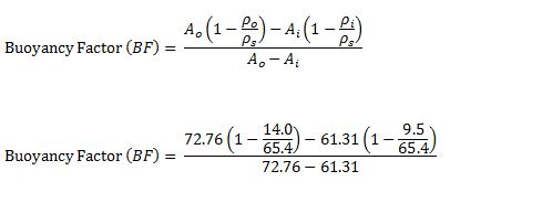
Buoyancy factor with different fluid inside and outside of tubular is listed below;
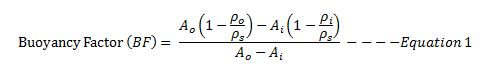
Where;
Ao is an external area of the component.
Ai is an internal area of the component.
ρo is fluid density in the annulus at the component depth in the wellbore.
ρi is fluid density in the component depth in the wellbore.
ρs is steel weight density. Steel density is 65.4 ppg.
If you can the same mud weight inside and outside, the equation 1 will be like this
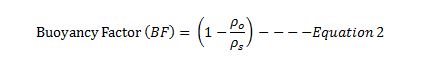
This is the same relationship as this article buoyancy factor calculation.
Let’s take a look at the following example to get more understanding.
Example
13-3/8” casing shoe was at 2,500’MD/2,000’TVD
9-5/8” casing was run to 6,800’MD/6,000 TVD.
9-5/8” casing weight is 40 ppf and casing ID is 8.835 inch.
Current mud weight is 9.5 ppg oil based mud.
The well bore diagram is show below (Figure 1).
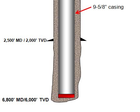
Figure 1 – Wellbore Diagram
The well is planned to cement from shoe to surface and the planned cement weight is 14.0 ppg. The displacement fluid is drilling mud currently used.
Please determine the following items.
- Air weight of casing string
- Buoyed weight of casing in drilling mud
- Buoyed weight of casing when cement is inside casing and drilling mud is outside casing
- Buoyed weight of casing when cement is outside casing and drilling mud is inside casing
Air weight of casing string
Air weight of casing string, lb = length of casing, ft × casing weight, lb/ft
Air weight of casing string, lb = 6,800 × 40 = 272,000 lb
Buoyed weight of casing in drilling mud

Figure 2 – Buoyed Weight When Submersed In Drilling Mud
Buoyed weight = Buoyancy Factor (BF) × Air Weight of Casing
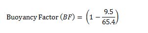
Buoyancy Factor (BF) = 0.855
Buoyed weight = 0.855 × 272,000 = 232,489 lb
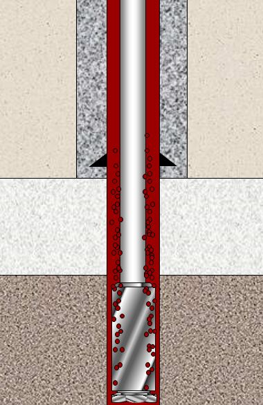
Buoyed weight of casing when cement is inside casing and drilling mud is outside casing
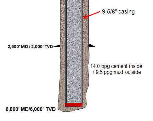
Figure 3 – Buoyed weight of casing when cement is inside casing and drilling mud is outside casing
We will apply the Equation-1 for this case.
Ao is an external area of the component.
Ao = π × (Outside Diameter of casing)2 ÷ 4
Ao = π × (9.625)2 ÷ 4 = 72.76 square inch
Ai is an internal area of the component.
Ai = π × (Inside Diameter of casing)2 ÷ 4
Ai = π × (8.835)2 ÷ 4 = 61.31 square inch
ρo = 9.5 ppf (mud in the annulus)
ρi = 14.0 ppg (cement inside casing)
ρs = 65.4 ppg.
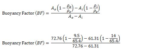
Buoyancy Factor (BF) = 1.22
Buoyed weight = 1.22 × 272,000 = 331,840 lb
Buoyed weight of casing when cement is outside casing and drilling mud is inside casing
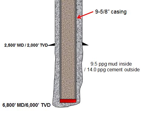
Figure 4 – Buoyed weight of casing when cement is outside casing and drilling mud is inside casing
We will apply Equation-1 for this case as well.
All the calculation parameters are the same.
Ao = π × (9.625)2 ÷ 4 = 72.76 square inch
Ai = π × (8.835)2 ÷ 4 = 61.31 square inch
ρo = 9.5 ppg (mud in the annulus)
ρi = 14.0 ppg (cement inside casing)
ρs = 65.4 ppg.
Buoyancy Factor (BF) = 0.42
Buoyed weight = 0.42 × 272,000 = 114,240 lb
Conclusion: At different stage of the well, you may have different buoyed weight depending on density of fluid inside and outside of the component and it is not always that buoyed weight is less than air weight.
Reference book =>  Formulas and Calculations for Drilling Operations