Let’s apply U-Tube concept

After learning about U-tube concept, let’s get a example in order to understand clearly about physical meaning of U-tube. This is very important concept so you need to clear about it.

Mud weight inside drill pipe is 9.8 PPG is all the way to bit and mud weight in the annulus is 9.2 PPG all the way to surface. Hole depth is 10,000’MD/8500’TVD. The well is shut in and drill pipe pressure is equal to 0 psi. Determine casing pressure.

According to U-tube concept, both sides (casing and drill pipe) have the same bottom hole pressure so we can write the equation to describe the U-tube concept as shown below;

SP (casing) + HP (casing) = BHP = SP (drill pipe) + HP (drill pipe)

At drill pipe side: BHP = 0 psi (Drill pipe Pressure) + 0.052×9.8×8,500 (Hydrostatic Pressure at drill pipe side) = 4,331 psi

At casing side: BHP = 4,331 psi = (Casing Pressure) + 0.052×9.2×8,500 (Hydrostatic Pressure at casing)

With this relationship (SP (casing) + HP (casing) = BHP = SP (drill pipe) + HP (drill pipe) ),we can solve casing pressure.

4331 = Casing Pressure + 4066

Casing Pressure = 4331 – 4066 = 265 psi

U tube

Ref books: 

Lapeyrouse, N.J., 2002. Formulas and calculations for drilling, production and workover, Boston: Gulf Professional publishing.

Bourgoyne, A.J.T., Chenevert , M.E. & Millheim, K.K., 1986. SPE Textbook Series, Volume 2: Applied Drilling Engineering, Society of Petroleum Engineers.

Mitchell, R.F., Miska, S. & Aadny, B.S., 2011. Fundamentals of drilling engineering, Richardson, TX: Society of Petroleum Engineers.

Understand U-Tube Concept and Importance of U-Tube

We can use the behavior of one of the fluid columns to describe behavior regarding what is happening in another side of fluid column, if two fluid columns are connected at bottom. Basically, this situation is simply described in common oil field name as “U Tube”.

In oil field especially drilling business, “U Tube” can be considered as a string of pipe (drill pipe and tubing) is in a wellbore and fluids are able to pass inside of string of pipe (drill pipe and tubing) and the annulus (area between wellbore and string of pipe). The figure 1 below demonstrates “U Tube” in our drilling business.

Figure 1 - U-Tube Diagram Represents Both Sides of Fluid Columns

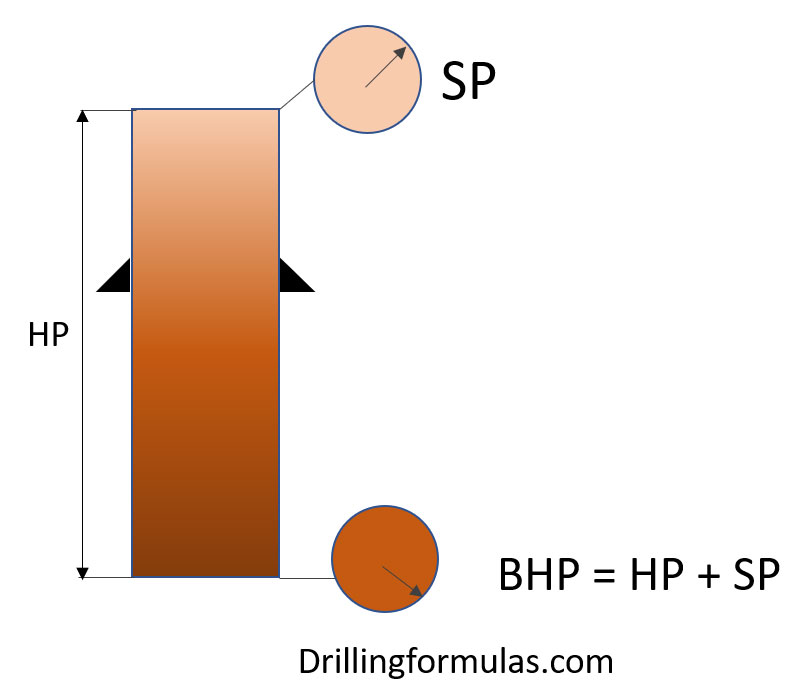
Figure 1 – U-Tube Diagram Represents Both Sides of Fluid Columns

A horizontal tube connects the right-hand side of the U-Tube and fluid levels in both columns should equalize when a fluid with consistent density is added. Furthermore, the hydrostatic pressure should be equal at the bottom of both columns. The pressure found at the base of both columns is considered ‘bottomhole pressure’. To replicate the opening through the nozzles in the bit, the opening at the base exists.

The mathematical relationship for this is shown below;

BHP = HP + SP

Where;

BHP = bottomhole pressure

HP = hydrostatic pressure

SP = surface pressure

With the U-tube concept applied, both sides of fluid columns can be described with the equation below;

 BHP = SIDPP + HP string = SICP + HP annulus

Where;

BHP = bottomhole pressure

SIDPP = shut in drillpipe pressure

HP string = hydrostatic pressure  in drill string

SICP = shut in casing pressure

HP annulus = hydrostatic pressure in annulus

When fluid density in both columns is equal, U-Tubes can be relatively simple. Surface pressures on the drillpipe and casing sides will be the same when the drillpipe and casing are themselves full of the same fluid density. However, U-Tubes become more difficult when fluids with varying densities are found in the columns. Despite the same BHP, both HP and SP will differ.

With hydrostatic and surface pressure equal in both columns, U-Tubes aren’t too interesting because both columns are filled with fluids of the same density. For example, when the annulus and drillpipe contain the same weight drilling mud while a bit is run to the hole’s bottom. The hydrostatic pressure is equal at both the casing and drillpipe side, fluid levels are static at the top, and the surface pressure on the drillpipe and casing sides are zero.

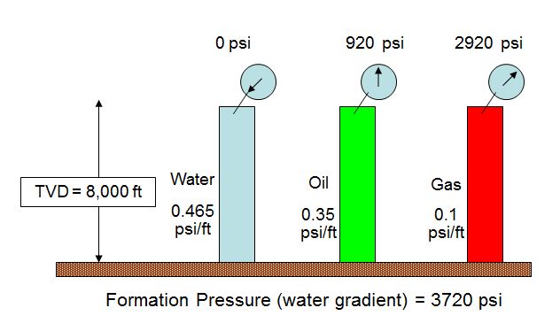
On the other hand, when columns are occupied by fluids of different densities, there’s likely to be a difference in both surface pressure and hydrostatic pressure in both columns (drillstring and casing side). For example, this is commonly seen in a kick with the bit on bottom as you can see from the figure 2 diagram. As formation pressure increases above hydrostatic pressure (generated by mud in the well), it kicks. The well will stop flowing if it’s shut-in; a surface pressure on the drillpipe gauge is then a reflection of the pressure underbalance. As opposed to drilling mud in the annulus, the fluid now contains lighter weight formation fluid and this leads to a reduction in total hydrostatic pressure (within the annulus). The shut-in casing pressure increases above shut-in drillpipe pressure to compensate to the underbalanced in the annulus side compared to the drillpipe side.

Figure 2 - U-Tube Diagram Represents Both Sides of Fluid Columns with Gas Kick

Figure 2 – U-Tube Diagram Represents Both Sides of Fluid Columns with Gas Kick

Why is U-Tube very important?

It is very vital to keep a basic concept of U-Tube in mind.

If there are two different fluids between inside of string and annulus, fluids always flow from a higher pressure area to a lower pressure.

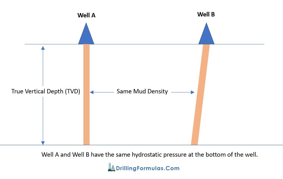
If the system is NOT closed, lighter fluid will be flown out and it will be stopped when system pressure is stabilized (see the figure 3 below).

Figure 3 - U-Tube Diagram Represents Both Sides of Fluid Columns Without a Closed System

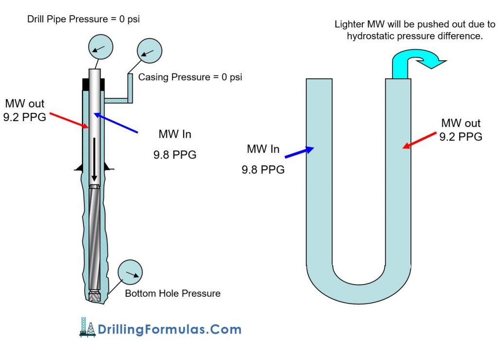
Figure 3 – U-Tube Diagram Represents Both Sides of Fluid Columns Without a Closed System

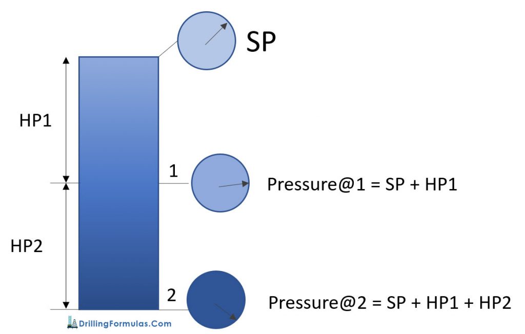
If the system is closed, for example the well shut in, pressure must be the same at the bottom point where both sides of U-tube are connected . Therefore, drill pipe pressure and casing pressure (annulus pressure) will be responded based on fluid in each side and formation pressure at bottom hole (see the figure 4 below).

Figure 4 demonstrates different in hydrostatic pressure between drill pipe and casing when mud weight 9.8 ppg is pumped to the bit and the well is shut in. This example helps understand how to use the equation to solve the problem.

The calculation is shown below.

BHP = SIDPP + HP string = SICP + HP annulus

BHP = 0 + (0.052 × 10,000  × 9.8) = 5,096 psi

5,096 psi = SICP + (0.052 × 10,000  × 9.2)

5,096 psi =  SICP + 4,784 psi

SICP = 312 psi

Note – you can find more information about hydrostatic pressure calculation here – Understand Hydrostatic Pressure

Figure 4 - U-Tube Diagram Represents Both Sides of Fluid Columns With a Closed System

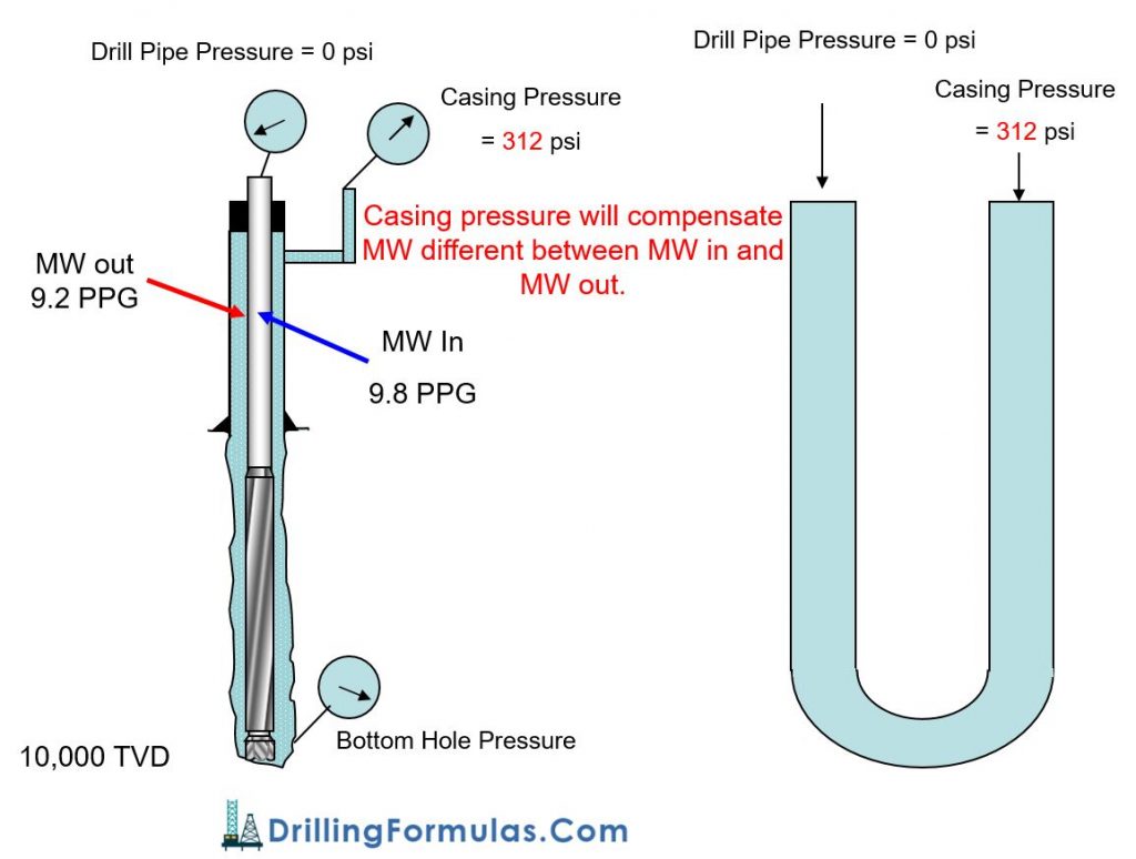
Figure 4 – U-Tube Diagram Represents Both Sides of Fluid Columns With a Closed System

The U-Tube concept can be widely applied in many drilling and workover application such as well control, cementing, hole monitoring, pulling out of hole, pumping slug, etc.

Ref books: 

Lapeyrouse, N.J., 2002. Formulas and calculations for drilling, production and workover, Boston: Gulf Professional publishing.

Bourgoyne, A.J.T., Chenevert , M.E. & Millheim, K.K., 1986. SPE Textbook Series, Volume 2: Applied Drilling Engineering, Society of Petroleum Engineers.

Mitchell, R.F., Miska, S. & Aadny, B.S., 2011. Fundamentals of drilling engineering, Richardson, TX: Society of Petroleum Engineers.

Bottom Hole Pressure Relationship

This article will show you about bottom hole pressure relationship because this concept is very important for well control concept. The bottom hole pressure is a summation of all the pressure acting on the bottom hole.

Bottom Hole Pressure (BHP) = Surface Pressure (SP) + Hydrostatic Pressure (HP)

The image below demonstrates the relationship of bottom hole pressure.

Note: BHP created by hydrostatic column of drilling fluid is the primary well control in drilling.

Looking more into details,

If BHP is more than FP (formation pressure), this situation is called “Overbalance”.

If BHP is equal to FP (formation pressure), this situation is called “Balance”.

If BHP is less than FP (formation pressure), this situation is called “Underbalance”.

For more understanding, please follow this example below it demonstrates the relationship of BHP, SP and HP.

Bottom Hole Pressure (BHP) = Surface Pressure (SP) + Hydrostatic Pressure (HP)

Bottom Hole Pressure Relationship 2

We assume that formation pressure is normal pressure gradient of water (0.465 psi/ft) so formation pressure at 8000’ TVD = 8000 ft x 0.465 psi/ft = 3720 psi. Click here to learn how to calculate hydrostatic pressure in oilfield.

The first case: Hydrostatic column is water which is equal to formation pressure gradient so SP is equal to 0 psi

The second case: BHP is still be water gradient but fluid column is oil (0.35 psi/ft) which is lower density than water gradient (0.465 psi/ft). Therefore, in order to balance BHP, we need Surface Pressure (SP) of 920 psi (SP = 3720 – (0.35 x 8000)).

The third case: BHP is still be water gradient but fluid column is gas (0.1 psi/ft) which is even lower density than water gradient (0.465 psi/ft). Therefore, in order to balance BHP, we need Surface Pressure (SP) of 2,920 psi (SP = 3720 – (0.1 x 8000)).

According to the example, Surface Pressure (SP) will compensate the lack of hydrostatic pressure (HP) in order to balance formation pressure (FP).

References

Cormack, D. (2007). An introduction to well control calculations for drilling operations. 1st ed. Texas: Springer.

Crumpton, H. (2010). Well Control for Completions and Interventions. 1st ed. Texas: Gulf Publishing.

Grace, R. (2003). Blowout and well control handbook [recurso electrónico]. 1st ed. Paises Bajos: Gulf Professional Pub.

Grace, R. and Cudd, B. (1994). Advanced blowout & well control. 1st ed. Houston: Gulf Publishing Company.

Watson, D., Brittenham, T. and Moore, P. (2003). Advanced well control. 1st ed. Richardson, Tex.: Society of Petroleum Engineers.

Understand Hydrostatic Pressure

In a well, any pressure created by a static column of fluid is called ‘Hydrostatic Pressure’ (HP); at any given True Vertical Depth (TVD). With ‘hydro’ representing water, which exerts pressure, ‘static’ means it has no movement. Any pressure developed by a column of fluid that isn’t moving, therefore, can be considered hydrostatic pressure; fluid in this sense can be either liquid or gas.

The relationship of hydrostatic pressure is shown in the equation below.

HP (Hydrostatic Pressure) = density x g (gravity acceleration) x h (True Vertical Depth, TVD)

In oilfield term, the formula above is modified so that people can use it easily. The formulas are as follows:

HP (Hydrostatic Pressure) = Constant x MW (Mud Weight or Mud Density)  x TVD (True Vertical Depth)

HP (psi)  = 0.052 x MW (ppg) x TVD (ft) ** Most frequent used in the oilfield **

HP (psi) = 0.007 x MW (pcf) x TVD (ft)

HP (kPa) = 0.00981 x MW (kg/m3) x TVD (m)

Depending on which unit is used for calculation, there are several conversion factors such as 0.052, 0.007, 0.00981 for instant as you can see from the equations above.

According to the equations above, Hydrostatic Pressure is not a function of hole geometry. Only mud weight and True Vertical Depth (TVD) affect on Hydrostatic Pressure. For example (a picture below); well A and well B have the same vertical depth. With the same mud density in hole, the bottom hole pressure due to hydrostatic pressure is the same. The only different between Well A and Well B is mud volume.

This concept is basic and very important for many aspects such as well control, balance cementing, u-tube, etc.

You can learn more about hydrostatic pressure calculation from the following article – Hydrostatic Pressure Calculation

Pressure in a well

In a static condition

  • Pressure at any depth = Hydrostatic Pressure (HP) + Surface Pressure (SP)
  • Pressure between 2 points is HP between these points

The diagram below demonstrates the relationship of pressure in a well.

At point 1, Pressure@1 = Surface Pressure (SP) + Hydrostatic Pressure @ 1 (HP1)

At point 1, Pressure@2 = Surface Pressure (SP) + Hydrostatic Pressure@1 (HP1) + Hydrostatic Pressure@2 (HP2)

Ref books: 

Lapeyrouse, N.J., 2002. Formulas and calculations for drilling, production and workover, Boston: Gulf Professional publishing.

Bourgoyne, A.J.T., Chenevert , M.E. & Millheim, K.K., 1986. SPE Textbook Series, Volume 2: Applied Drilling Engineering, Society of Petroleum Engineers.

Mitchell, R.F., Miska, S. & Aadny, B.S., 2011. Fundamentals of drilling engineering, Richardson, TX: Society of Petroleum Engineers.

Decrease oil/water ratio

Decrease oil/water ratio: The concept of decrease oil water ratio is to increase water volume in the system without any changes in oil volume to meet new oil water ratio.

How can we decrease oil water ratio to 70/30?

Let’s make it simple so I still use the same information as my previous post. We start with 100 bbl of mud and we have the following information from the retort analysis.

Retort analysis:

% by volume oil = 56

% by volume water = 14

% by volume solids = 30

According to this retort analysis, the oil water ratio is 80/20 (learn how to calculate oil water ratio from a retort analysis) and there are 56 bbl of oil, 14 bbl of water and 30 bbl of solid from 100 bbl of mud.

In order to decrease oil water ratio, water must be added but oil volume remains the same. Therefore, 56 bbl of oil will represent 70% of oil ratio for the new system. We give X equals to the new total liquid volume (combination of oil and water volume).

Then; 70 = (56×100) ÷X

X = 80.0 bbl

Total liquid volume is equal to 80.0 bbl.

Oil volume is still the same but water volume will be added into the system. With this concept, the volume of water will added into the system can be described with the following relationship;

Water added = new total liquid volume – original volume

Water added = 80 – 70 = 10 bbl

If you have the total mud volume of 300 bbl, you will need 30 bbl of water added (10 x 300 ÷ 100) in order to decrease oil water ratio from 80/20 to 70/30


Ref book: Formulas and Calculations for Drilling, Production and Workover, Second Edition