Coiled Tubing Equipment Overview

Coiled tubing was developed in 1970s and is one of the most important pieces of well intervention equipment in the oil and gas industry. There are several different types of it available in the industry market with several different designs of a coiled tubing unit; however, the components of a coiled tubing unit are very similar. The main differences are performance capabilities and hydraulic power control systems. This article will give an overview of the essential components of a coiled tubing unit. (Read about the history of coiled tubing here – Introduction to Coiled Tubing (CT) in Oil and Gas)

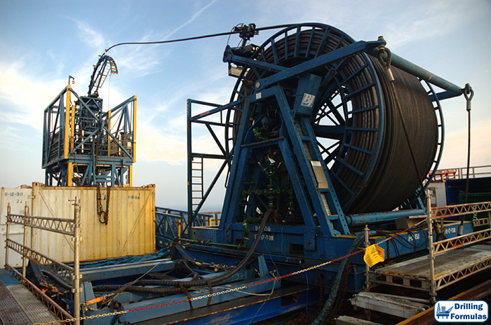
Figure 1 shows the mounted truck coiled tubing unit, which is normally used for the land operation and Figure 2 is the coiled tubing unit used for operating in an offshore environment.

Figure 1 – Coiled Tubing Unit on a Truck (Courtesy of Stewart & Stevenson)

Figure 2 – Offshore Coiled Tubing Unit (Courtesy of NOV)

Continue reading

Introduction to Coiled Tubing (CT) in Oil and Gas

Development of the coiled tubing like we know it today started in early 1960’s. Now it is an important component of various workover and service applications. While still the use of Coil Tubing is about 75% in workover/service applications, the technical advancements have resulted in an increase in utilization of Coil tubing in drilling as well as completion applications.

Ability of performing remedial work on live well was an important driver associated with development of Coil Tubing. In order to achieve this feat, there was a need to overcome three different technical challenges: These were:

  • Continuous conduit that is capable of being inserted in to wellbore (the CT string).
  • Means of running the CT string and retrieving it in to or out of wellbore when under pressure (the injector head).
  • Device that is capable of giving a dynamic seal around tubing string (packoff or stripper device)
Coiled Tubing Unit

Coiled Tubing Unit (Credit: ShutterStock)

The Origin of Coiled Tubing Continue reading

Tubing Length Change due to Buckling

When tubing is freely suspended, it can be buckled by an upward force applied at the bottom of tubing. A section of tubing exposed to compression force will have a chance of being buckled. However, a part which is under tension will not face a buckle issue.

The neutral point is the boundary below which buckling can possibly be occurred and above which buckling will not happen.


Figure 1 - Wellbore Diagram with Tubing Buckling Due to Compression Force

Figure 1 – Wellbore Diagram with Tubing Buckling Due to Compression Force

Continue reading

Tubing Length Change due to Thermal Load

Difference in temperature causes steel to contract or expand. If tubing is free to move, length of the tubing will be either longer or shorter due to thermal expansion. On the other hand, if the tubing is not free to move, there will be a change in axial force due to the temperature effect.

Figure 1 illustrates an increase in length due to heat and Figure 2 demonstrates a decrease in length because of cooling.

Figure 1 – Tubing Lengthen by Temperature Increase

Figure 1 – Tubing Lengthen by Temperature Increase

Figure 2 - Tubing Shorten by Temperature Decrease

Figure 2 – Tubing Shorten by Temperature Decrease

Continue reading

Tubing Length Change due to Ballooning

Ballooning is a change in average pressure which causes a radial contraction or swelling. If the tubing is free to move, the length of tubing will be either longer or shorter. If tubing cannot be moved, stress will be created in the tubing body.

Figure 1 illustrates ballooning of tubing. This will happen when internal pressure is higher than external pressure. Tubing will shorten if the tubing is free to move. If the tubing cannot be moved, ballooning will create a tension force on the packer.

Figure 1 – Ballooning

Figure 1 – Ballooning

Continue reading