What is slug mud? How much volume and weight of slug mud should be?

Slug Mud: It is heavy mud which is used to push lighter mud weight down before pulling drill pipe out of hole. Slug is used when pipe became wet while pulling out of hole.

Normally, 1.5 to 2 PPG over current mud weight is a rule of thumb to decide how much weight of slug should be. For example, current mud weight is 10 PPG. Slug weight should be about 11.5 to 12 PPG.

Normally, slug is pumped to push mud down approximate 200 ft (+/2 stands) and slug volume can be calculated by applying a concept of U-tube (see a figure below)

Volume of slug can be calculated by this following equation:

This equation expresses that the higher slug volume, the deeper of dry in drill pipe is met. As per the above equation, length of dry pipe can be substituted by 200 ft.

In normal practice, slug volume pumped to clean drill pipe is around 15-25 bbl depending on drillpipe size. Moreover, it also depends on situations because sometime mud in annulus side may be heavier than measured MW due to cutting, drilling solid contaminated in mud, hence more slug volume is needed.

Ref books: 

Lapeyrouse, N.J., 2002. Formulas and calculations for drilling, production and workover, Boston: Gulf Professional publishing.

Bourgoyne, A.J.T., Chenevert , M.E. & Millheim, K.K., 1986. SPE Textbook Series, Volume 2: Applied Drilling Engineering, Society of Petroleum Engineers.

Mitchell, R.F., Miska, S. & Aadny, B.S., 2011. Fundamentals of drilling engineering, Richardson, TX: Society of Petroleum Engineers.

Drilling Mud Motor Concerns and Practices

I got some questions from Mike R Hogolan regarding mud motor concerns. The questions are very interesting and I would like to share some answers to you all as well.

Why is it more difficult to steer a motor the deeper section of wellbore?

It is harder to steer the motor when well is deeper because the friction exerted from formation to drillstring in open hole section increases. Motor cannot be effectively used to drilled deeper along all well path because high friction force exerted on BHA, higher temperature as well deeper can cause rotor, made of synthetic rubber, failure.

Why is the most effective steering by using the pump pressure gauge rather than the weight indicator?

Driller will use the pump pressure gauge as opposed to the weight indicator because WOB is not accurate while steering. High friction force between drillstring and formation is created when steering. If there are consistent circulating mud properties, flow rate and formation characteristics should be within the normal motor operating range, an increase or decrease in weight on bit will result in a directly proportional increase or decrease in pump pressure.

What is meant by stalling a motor?
Stalling motor means that steerable motor stalls at bottom hole (can not rotate) because of higher WOB, harder formation, not enough torque to turn the bit, etc. When motor stalling, stand pipe pressure increases significantly and ROP significantly drops.

What are indicators a motor is wearing out?
Indicators demonstrate a motor worn out as follows:
• Lower ROP without any changes of parameter on surface
• Difficult to control well direction as per designed well trajectory
• Increase in pump pressure
• Easily motor stall

Reference books: Directional Drilling Books

What are the differences between steering (orienting or sliding) and rotating?

Steering (orienting or sliding) is drilling with mud downhole steerable mud motor. Drilling with the steerable motor does not rotate drill pipe because it uses hydraulic power to drive down hole motor and bit. Steering is used in order to control well direction.

Rotating is drilling with Topdrive or rotary table and drillstring is rotated in order to gouge the hole. Rotary drilling will be used when straight hole direction is needed.

Comparing between steering and rotating, steering can create dog leg more than rotating because mud motor incorporating with bend housing is designed to directionally drill to the specified direction; however, when Rotating, BHA is stiffer and has tendency to hold the direction.

Rotating ROP is always faster than steering ROP by these following reasons:
• Friction force exerts on stable drill string when steering is always more than rotating.
• When steering, WOB is limited. Motor can be stalled or worn out if WOB excesses.
• Direction of well must be controlled carefully that means well can not be drilled faster.

Reference books: Directional Drilling Books

What is the difference between drill solids and barite?

Learn the difference between drill solids and barite and how these 2 kinds of weighting material will affect drilling operation.

Drill Solid: It is solid particles from formation generated while drilling. Its specific gravity is about 2.6 which is normally defined as Low Gravity Solid (LGS). Drill solid can increase mud weight; however, it will degrade mud properties such as Yield Point, viscosity, gel strength, etc. If mud excessively gets drill solid, drilling fluid properties especially rheology (Yield Point, viscosity) will be higher and mud cake with a lot of drill solid will be poor quality. Higher rheology will lead to more required energy in order to make circulation. In addition, poor mud cake can also lead to pipe struck situation.

In order to control drill solid content in mud, solid control equipment as shale shakers, desanders, desilters and centrifuges must be operated properly and effectively.

Barite: It is the weighting agent with specific gravity about 4.2 normally called High Gravity Solid. Both Drill solid and Barite are able to be weighting agent; however, Barite does not degrade other mud properties such as PV, YP, gel strength, etc.

Reference books: Drilling Fluid Books

Drilling Fluid Properties

Drilling fluid properties are essential information that everybody should understand.

Density: Mud density is the weight per unit volume of mud and normally it is reported in Pound Per Gallon (PPG). Mud density is used for providing hydrostatic pressure to control well for drilling operation.

Viscosity: It is defined as the internal resistance of fluid flow. There are 2 types of viscosity which are Funnel Viscosity and Plastic Viscosity.

1) Funnel Viscosity: It is time, in seconds for one quart of mud to flow through a Marsh funnel which has a capacity of 946 cm3 (See Figure 1). A quart of water exits the funnel in 26 seconds. This is not a true viscosity, but serves as a qualitative measure of how thick the mud sample is. The funnel viscosity is useful only for relative comparisons.

Figure 1 Marsh Funnel

2) Plastic Viscosity (PV): A parameter of the Bingham plastic rheological model (See Figure 3). PV is the slope of the shear stress-shear rate plot above the yield point (See Figure 4). Viscometer is equipment to measure Plastic Viscosity (See Figure 2). Plastic Viscosity is derived from the 600 rpm reading minus the 300 rpm reading and PV is in centipoises (cp). A low PV indicates that the mud is capable of drilling rapidly because of the low viscosity of mud exiting at the bit. High PV is caused by a viscous base fluid and by excess colloidal solids. To lower PV, a reduction in solids content can be achieved by dilution.

There are many rheology models shown in Figure 3. Normally Bingham Plastic Model is used to describe mud properties as Plastic Viscosity and Yield Point (See Figure 4).

Figure 2 Viscometer

Figure 3 Rheology Model (Ref  slb.com)

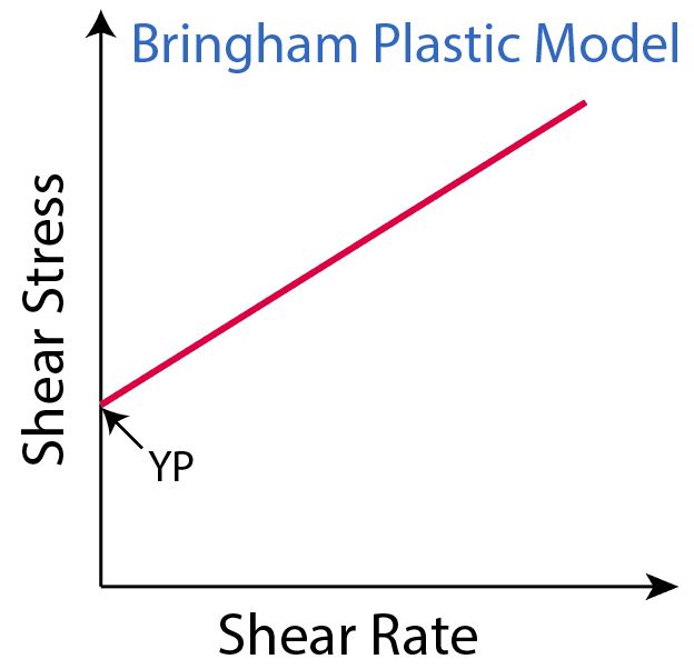
Figure 4 Bingham Plastic Model describes PY and VP

Yield Point: Physical meaning is the resistance to initial flow, or the stress required starting fluid movement. The Bingham plastic fluid plots as a straight line on a shear-rate (x-axis) versus shear stress (y-axis) plot, in which YP is the zero-shear-rate intercept (PV is the slope of the line). YP is calculated from 300-rpm and 600-rpm viscometer dial readings by subtracting PV from the 300-rpm dial reading and it is reported as lbf/100 ft2. YP is used to evaluate the ability of mud to lift cuttings out of the annulus. A higher YP implies that drilling fluid has ability to carry cuttings better than a fluid of similar density but lower YP.

Gel Strength: It is the ability of fluid to suspend fluid while mud is in static condition. Before testing gel strength, mud must be agitated for awhile in order to prevent precipitation and then let mud is in static condition for a certain limited time (10 seconds, 10 minutes or maybe 30 minutes) and then open the viscometer at 3 rpm and read the maximum reading value. In a morning report, there are 3 values of gel strength, which are Gel 10sec (lbf/100 ft2), Gel 10 mins (lbf/100 ft2) and Gel 30 mins (lbf/100 ft2).

Ph: This value tells the acid of drilling fluid. Ph paper is used to measure Ph.

Electrical Stability (ES): This value reflects to the stability of emulsion of SDF. If water disperses well in oil phase (good emulsion), the resistivity of drilling fluid will be higher. In contrast, if water disperses badly in oil phase (bad emulsion), the resistivity of drilling fluid will be lower. As the concept above, applied Ohm’s law (V=IR), electricity from the electrical stability meter is emitted in to mud and voltage is measured by the electrical probe. Normally if the measured voltage is higher than 500 volt, the electrical stability is good.

Figure 5 Electrical Stability Meter

CaCl2 Concentration: Cl+ can prevent formation swell hence this value must be maintained. It is measured by a titration test by using silver nitrate as titrant with potassium chromate as the endpoint indicator and when titration reaches the equilibrium point mud will change into red.

Retort Test: There are 2 values that are Saraline Water Ratio (SWR) and Solid Content (LGS, Barite) obtained from this testing. Mud is retorted in retort test skid at 950 F for 2 hrs. High temperature can vaporize liquid phase into gas phase and then gas phase will be transferred to a condenser and condense in liquid form. Liquid is stored in a tube that has a level indicator to see how much of water and oil (saraline) extracted. Moreover, solid left in the retort reflects the solid content in mud.

Figure 6 Retort Test Skid

HTHP Fluid Loss: This test is conducted for testing fluid loss behavior of mud. Mud is pressed through filter paper located in the HTHP filter press at 300 F with differential pressure at 500 psi for 30 mins. Thickness of filter cake stuck in filter paper should be less than 2 ml.

Figure 7 HTHP filter press

Reference books: Drilling Fluid Books