About DrillingFormulas.Com

Working in the oil field and loving to share knowledge.

How Does Deep Water Drilling Work

Nowadays deep water drilling is one of vital players for oil and gas exploration and production industry and there are many people who would like to know how deep water drilling works. We’ve found one excellent VDO demonstrates the deep water drilling process in a simple way. This VDO will give you clearer picture about the topic and we also add full VDO transcript in order to help more people understand the content clearly. We wish you would enjoy learning from this VDO and please feel free to give us feedback : )

Full VDO Transcript – How Does Deep Water Drilling Work

deep-water-drilling

Credit: Image from Wikipeida

How does the deep sea drilling vessel Chikyu drill into the sea floor? When the vessel arrives at the drilling site it receives a satellite signal that helps the vessel moves into the exact position required. The vessel has six propellers that rotate a full 360 degrees and keep the vessel in one position preventing it from drifting due to the wind, waves or sea current.

Continue reading

Maximum ROP Before Fracture Formation

In this topic, we will apply the effective mud density formula to determine maximum ROP before fracturing formation.

Figure 1 - Max ROP before Fracturing FormationFigure 1 – Max ROP before Fracturing Formation


These two equations that will be used to determine the maximum ROP are listed below;

Effective mud density due to cuttings in the hole can be determined by the empirical equation below;

equation 1

Where;

ρeff is effective mud density in ppg.

ρm is mud density in ppg.

Q is flow rate in gpm.

ROP is rate of penetration in fph.

db is wellbore diameter or bit diameter in inch.

Continue reading

Increase In Mud Weight Due To Cutting

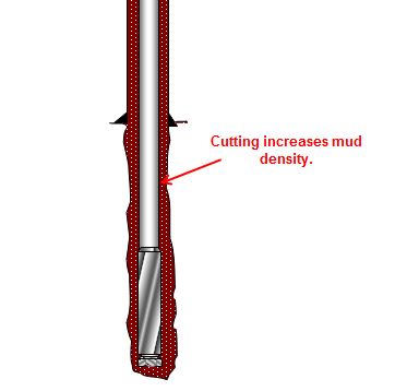
Cutting generated while drilling will increase drilling fluid density and it will finally affect equivalent circulating density while drilling. In this topic, we will talk about how to determine mud weight increase due to cutting.

 Figure 1 - Cutting Increases Mud Density

Figure 1 – Cutting Increases Mud Density


Effective mud density due to cuttings in the hole can be determined by the empirical equation below;

euqation pm

Continue reading

How To Free Stuck Pipe (Oilfield)

This article is a summary of how to free stuck pipe caused by three main mechanisms which are wellbore geometry, differential sticking and packing/bridging off. It will give you some ideas which you can apply for your operation.

How-to-free-a-stuck-pipe2


Free Stuck Pipe Caused By Wellbore Geometry

These following instructions are guide lines on how to free the stuck drill string caused by wellbore geometry.

What should you  do to free the stuck pipe caused by wellbore geometry ?

• If the drill string gets stuck while moving up, jar down with maximum trip load and torque can be applied into drill string while jarring down. Be caution while applying torque, do not exceed make up torque.

• On the other hand, if the drill string gets stuck while moving down, jar up with maximum trip load. DO NOT apply torque in the drill string while jarring up.

• Flow rate must be reduced while attempting to free the drill string. Do not use high flow rate because it will make the stuck situation became worse and you will not be able to free the pipe forever.

Continue reading

Buoyancy Factor Table Free Download

Buoyancy factor is the factor that is used to compensate loss of weight due to immersion in drilling fluid and you can find the calculation from here https://www.drillingformulas.com/buoyancy-factor-calculation/.

bf-table-facbook

We have created a simple table to help people determine the buoyancy factor quickly. Let’s take a look at the table. In Figure 1, it shows the main page and you can select the mud weight range from 4.0 ppg to 19.0 ppg.

 Figure 1- Main Page BF Table

Figure 1– Main Page BF Table

For instant, we choose 8.0 ppg and the table will show buoyancy from 8.0 – 8.9 ppg (Figure 2)

Figure 2 - Buoyancy Factor for 8 ppg Range

Figure 2 – Buoyancy Factor for 8 ppg Range

  Continue reading