


Referring to the previous section, primary well control is hydrostatic pressure bore that prevents reservoir influx while performing drilling operations (drilling, tripping, running casing/completion, etc). When primary well control is failed, it causes kick (wellbore influx) coming into a wellbore. Therefore, this situation needs special equipment which is called “Blow Out Preventer” or BOP to control kick.
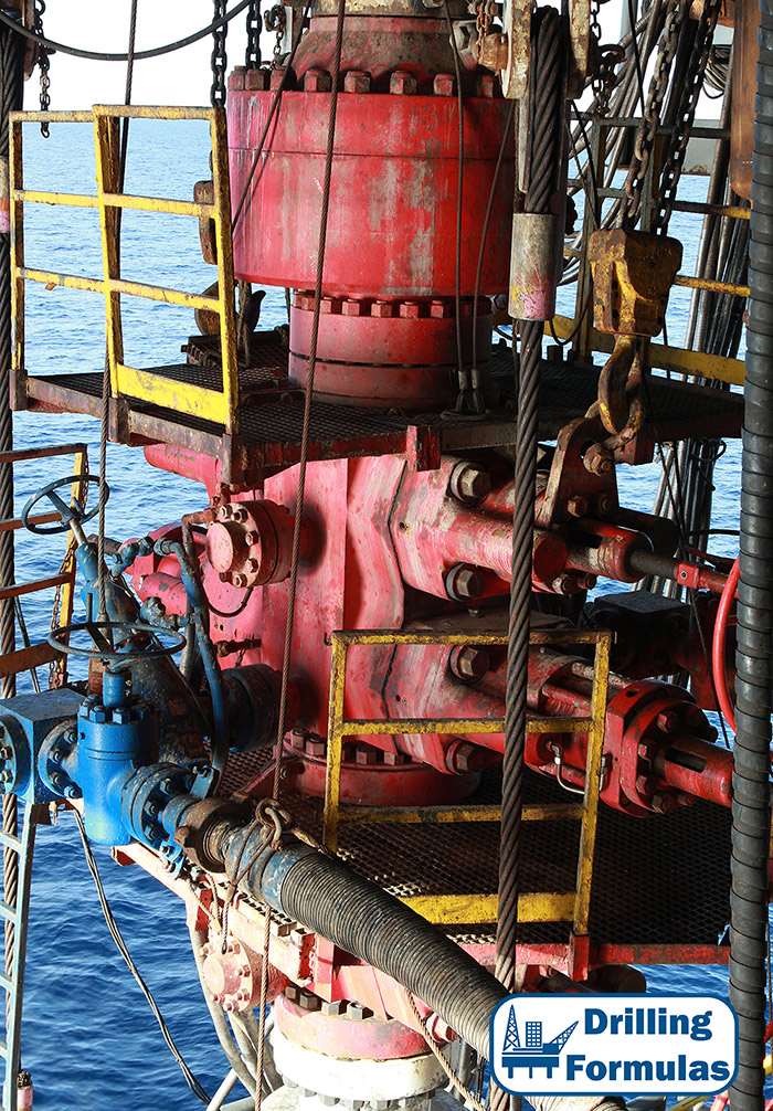
Blow Out Preventer
We can call that “Blow Out Preventer” or BOP is Secondary Well Control. Please also remember that BOP must be used with specific procedures to control kick such as driller method, wait and weight, lubricate and bleed and bull heading. Without well control practices for using BOP’s, it will just be only heavy equipment on the rig.
There are several types of “Blow Out Preventer” (BOP) which have different applications. we will talk about BOP categories later.
References
Coleman, S. (2018). Well Control Quiz Online. [online] Well Control Quiz Online – Test Your Well Control Knowledge for Free. Available at: http://wellcontrolquiz.com/ [Accessed 2 Aug. 2018].
Cormack, D. (2007). An introduction to well control calculations for drilling operations. 1st ed. Texas: Springer.
Crumpton, H. (2010). Well Control for Completions and Interventions. 1st ed. Texas: Gulf Publishing.
Grace, R. (2003). Blowout and well control handbook [recurso electrónico]. 1st ed. Paises Bajos: Gulf Professional Pub.
Grace, R. and Cudd, B. (1994). Advanced blowout & well control. 1st ed. Houston: Gulf Publishing Company.
Watson, D., Brittenham, T. and Moore, P. (2003). Advanced well control. 1st ed. Richardson, Tex.: Society of Petroleum Engineers.


