Deviating the Wellbore by Jetting and Whipstock (Directional Drilling)

To deviate a well from a vertical path, and get it to follow an intended well trajectory , it is necessary to put some side force onto the bit. The amount of this, as well as its direction, are vital in order to keep the bit to its intended path. Other factors will also have an influence, including the hardness of the rock which is being drilled, as well as bedding plane angles. There are numerous different ways of developing a controlled side force on the bit. Two of the earliest developed methods are whipstock and jetting which will be discussed in this article.

Jetting as the Directional Drilling Tool

A tricone drill bit possesses three drilling cones, with a nozzle in between each one. Should a large nozzle be set into a single nozzle pocket, and two smaller nozzles used alongside it, then the majority of the mud flow would pass through the larger nozzle. Drilling fluid will be ejected from the drill bit with a significant amount of force, and so long as the formation is not overly hard, will erode the rock in its path. As the large nozzle directs the majority of the flow to a single point, a pocket will be carved into the rock in this direction. The well may be deviated simply by aligning the bit in the necessary direction, and then circulating without rotation.

Once between 5-6 feet have been washed away, the bit is then rotated, and drilling continues as normal. This process can be repeated continuously until an angle of around 12° is produced, or until rock is reached which is too solid to jet through. Figure 1 to 3 illustrate a jetting operation by a rotary drilling assembly, which is used to allow the well to keep building an angle while drilling and rotating take place.

Figure 1 – Jet a well to desired direction

Continue reading

Directional Well Planning and Well Profile

The well planning process starts from geologists and reservoir engineers who decide the best place for the wellbore. They may only need to determine a single target, which will often be a tolerance of about 330 ft (100 m) around a certain target point. In this case, the angle at which the well enters the target can have various degree of deviation from the plan since a plan requires to hit only one target. On the other hand, it might be necessary for the well to penetrate multiple targets, with the final target being increasingly complex. This requires what is known as “geosteering”, a process which will be discussed later in the directional drilling series. The drilling engineer therefore needs to examine potential surface locations (if more than one is available) and design a well path which meets all necessary target requirements at the lowest possible cost. Cost can be minimized most effectively when there is a certain degree of flexibility when it comes to the surface location.

Continue reading

Magnetic Declination and Grid Convergent and Their Applications in Directional Drilling

This article will describe about Magnetic Declination and Grid Convergent and how to use them for directional drilling purposes.

Magnetic Declination

In the azimuth reference, three North references are Magnetic North, True North and Grid North (Figure 1). Since these 3 North references are not the same direction; therefore, it must be a correction in order to convert any Azimuth in the same reference. Two main concepts, which are magnetic declination and grid convergent, are used to AZI from the magnetic tool to the AZI referencing to the Grid North.

Figure 1 - True North, Magnetic North and Grid North

Figure 1 – True North, Magnetic North and Grid North

Continue reading

Shape of the Earth and Geodetic Datums for Directional Drilling

Directional drilling relies on mapping system to accurately identify location of the wells. Therefore, it is very important to learn the basics of mapping and other relevant information. This topic is about Geodetic Datum.

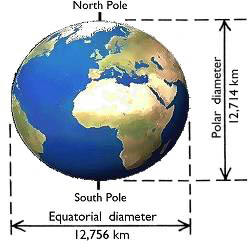
The Earth is not a complete sphere shape but it is actually Oblate Spheroid (“Spheroid”). It means that the shape of the Earth is almost a sphere. It can be proven from the fact that the equatorial diameter (the longest diameter) is approximately 12,756 km and the diameter from the North Pole to the South Pole is approximately 12,714 km (Figure 1). Additionally, the Earth has a different attitude based on location. So, people developed a model to help describe the Earth, which is called “Geodetic Datums”.

Figure 1 - Earth Shape

Figure 1 – Earth Shape

Continue reading