Scale Factor in UTM Mapping System and its Application in Directional Drilling

Scale factor represents distortion from a mapping system since the Earth is mapped into a flat surface, but the actual surface is in curvature. Figure 1 illustrates a scale factor with a reference location of the Earth’s surface. If the location is above the map projection plan, the scale factor will be less than 1.0. However, if the location is below the mapping projection, the scale factor will be more than 1.0. A scale factor less than 1 means that the actual distance on the Earth’s surface is longer than the actual distance on the map. Whereas, the scale factor of more than 1 demonstrates that the actual distance on the Earth is shorter than the map distance.

Figure 1 - Scale Factor

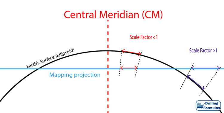
Figure 1 – Scale Factor

Continue reading

Universal Transverse Mercator Application in Directional Drilling

Universal Transverse Mercator (UTM) is one of the commonly used map projection methods in directional drilling. In UTM, the world is divided up into 60 zones between 84° North and 80° South and East-West from 180 degrees longitude. Then the Earth is flattened with the Zone 1 starting at 180 E-W longitude. Since the earth is divided into 60 zone so each zone has 6 degree wide. Figure 1 illustrates the concept of UTM and Figure 2 shows the UTM grid. This method will not cover the polar region.

Figure 1 - Universal Transverse Mercator Diagram

Figure 1 – Universal Transverse Mercator Diagram

Figure 2 - The Universal Transverse Mercator (UTM) grid

Figure 2 – The Universal Transverse Mercator (UTM) grid

Zones are numbers from 1 to 60 and the zone 31 has 0 degree meridian (Greenwich, England) on the left and 6 degree East on the right (Figure 3). Each one in UTM is divided into grid sections which cover 8 degrees of latitude and the system uses letters from C to X, excluding I and O.

Figure 3 - UTM zone 31

Figure 3 – UTM zone 31

Continue reading