Boyle’s Gas Law and Its Application in Drilling

Understand Boyle’s Gas Law

Boyle’s gas law states that at constant temperature, the absolute pressure and the volume of a gas are inversely proportional in case of constant temperature within a closed system.  Bolye’s law can be illustrate in the graph shown in figure 1.

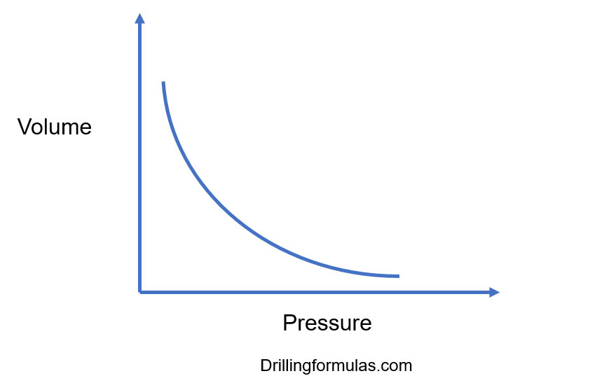
Figure 1 – Boyle’s Law

Well, we can describe the statement above into simple mathematics as following formula:

Boyle’s Gas Law

P x V = constant

Or express Boyle’s law in another term:

P1 x V1 = P2 x V2

Where;

P1 = Pressure at condition # 1

 V1 = Volume at condition # 1

P2 = Pressure at condition # 2

 V2 = Volume at condition # 2

Note: You can use any unit for Bolye’s gas law as long as P1 and P2 are the same unit and V1 and V2 are the same unit.

Let’s apply Boyle’s law into our drilling business

Calculate the volume of gas you will have on the surface, 14.7 psi for atmospheric pressure, when 1 bbl of gas kick is circulated out from reservoir where has formation pressure of 3,000 psi. Figure 2 and 3 shows the condition of this well.

Figure 2 – Gas Kick 1st condition at the bottom

Figure 3 – Gas Kick 2nd condition

Apply the Boyle’s Gas Law:

P1 x V1 = P2 x V2

P1= 3000 psi (reservoir pressure)

V1 = 1 bbl (volume at bottom hole)

P2 = 14.7 psi (atmosphere pressure)

V2 = ? (volume at surface)

P1 x V1 = P2 x V2

3000 x 1 = 14.7 x V2

V2 = 204 bbl

Figure 4 – Gas

References

Cormack, D. (2007). An introduction to well control calculations for drilling operations. 1st ed. Texas: Springer.

Crumpton, H. (2010). Well Control for Completions and Interventions. 1st ed. Texas: Gulf Publishing.

Grace, R. (2003). Blowout and well control handbook [recurso electrónico]. 1st ed. Paises Bajos: Gulf Professional Pub.

Grace, R. and Cudd, B. (1994). Advanced blowout & well control. 1st ed. Houston: Gulf Publishing Company.

Watson, D., Brittenham, T. and Moore, P. (2003). Advanced well control. 1st ed. Richardson, Tex.: Society of Petroleum Engineers.

Let’s apply U-Tube concept

After learning about U-tube concept, let’s get a example in order to understand clearly about physical meaning of U-tube. This is very important concept so you need to clear about it.

Mud weight inside drill pipe is 9.8 PPG is all the way to bit and mud weight in the annulus is 9.2 PPG all the way to surface. Hole depth is 10,000’MD/8500’TVD. The well is shut in and drill pipe pressure is equal to 0 psi. Determine casing pressure.

According to U-tube concept, both sides (casing and drill pipe) have the same bottom hole pressure so we can write the equation to describe the U-tube concept as shown below;

SP (casing) + HP (casing) = BHP = SP (drill pipe) + HP (drill pipe)

At drill pipe side: BHP = 0 psi (Drill pipe Pressure) + 0.052×9.8×8,500 (Hydrostatic Pressure at drill pipe side) = 4,331 psi

At casing side: BHP = 4,331 psi = (Casing Pressure) + 0.052×9.2×8,500 (Hydrostatic Pressure at casing)

With this relationship (SP (casing) + HP (casing) = BHP = SP (drill pipe) + HP (drill pipe) ),we can solve casing pressure.

4331 = Casing Pressure + 4066

Casing Pressure = 4331 – 4066 = 265 psi

U tube

Ref books: 

Lapeyrouse, N.J., 2002. Formulas and calculations for drilling, production and workover, Boston: Gulf Professional publishing.

Bourgoyne, A.J.T., Chenevert , M.E. & Millheim, K.K., 1986. SPE Textbook Series, Volume 2: Applied Drilling Engineering, Society of Petroleum Engineers.

Mitchell, R.F., Miska, S. & Aadny, B.S., 2011. Fundamentals of drilling engineering, Richardson, TX: Society of Petroleum Engineers.

Accumulator Capacity – Usable Volume per Bottle Calculation for Subsea BOP

For subsea applications, hydrostatic pressure exerted by the hydraulic fluid must be accounted for calculation.

th_277868

In this case, we assume water depth at 1500 ft, therefore hydrostatic pressure exerted by hydraulic fluid (hydraulic fluid pressure gradient = 0.445 psi/ft) = 0.445×1500 = 668 psi. Besides of that, the concept for calculation is as same as surface accumulator. So please take a look about how to calculate usable volume per bottle as following steps.

Step 1 Adjust all pressures for the hydrostatic pressure of the hydraulic fluid:

Pre-charge pressure = 1000 psi + 668 psi = 1668 psi

Minimum system pressure = 1200 psi + 668 psi = 1868 psi

Operating pressure = 3000 psi + 668 psi = 3668 psi

Step 2 Determine hydraulic fluid required to increase pressure from pre-charge pressure to minimum system pressure:

Boyle’s Law for ideal gase: P1 V1 = P2 V2

1668 psi x 10 = 1868 x V2

16,680 ÷1,868 = V2

V2 = 8.93 gal

It means that N2 will be compressed from 10 gal to 8.93 gal in order to reach minimum operating pressure. Therefore, 1.07 gal (10.0 – 8.93 = 1.07 gal) of hydraulic fluid is used for compressing to minimum system pressure.

Step 3 Determine hydraulic required increasing pressure from pre-charge to operating pressure:

P1 V1 = P2 V2

1668 psi x 10 gal = 3668 psi x V2

16,680 ÷ 3668 = V2

V2 = 4.55 gal

It means that N2 will be compressed from 10 gal to 4.55 gal in order to reach operating pressure. Therefore, 5.45 gal (10.0 – 4.55 = 5.45 gal) of hydraulic fluid is used for compressing to operating pressure.

Step 4 Determine usable fluid volume per bottle:

Usable volume per bottle = Total hydraulic fluid/bottle – Dead hydraulic fluid/bottle

Usable volume per bottle = 5.45 – 1.07

Usable volume per bottle = 4.38 gallons

Reference book: Well Control Books

Formulas and Calculations for Drilling, Production and Workover, Second Edition

Accumulator Capacity – Usable Volume per Bottle Calculation (Surface Stack)

Accumulator (Koomey) is a unit used to hydraulically operate Rams BOP, Annular BOP, HCR and some hydraulic equipment. There are several of high pressure cylinders that store gas (in bladders) and hydraulic fluid or water under pressure for hydraulic activated systems. The primary purpose of this unit is to supply hydraulic power to the BOP stack in order to close/open BOP stack for both normal operational and emergency situation. Stored hydraulic in the system can provide hydraulic power to close BOP’s in well control operation, therefore, kick volume will be minimize. Accumulators should have sufficient volume to close/open all preventers and accumulator pressure must be maintained all time.

koomey-unit

This post you will learn how to calculate usable volume per bottle by applying Boyle’s gas law:

Use following information as guideline for calculation:

Volume per bottle = 10 gal

Pre-charge pressure = 1000 psi

Operating pressure = 3000 psi

Minimum system pressure = 1200 psi

Pressure gradient of hydraulic fluid = 0.445 psi/ft

For surface application

Step 1 Determine hydraulic fluid required to increase pressure from pre-charge pressure to minimum:

Boyle’s Law for ideal gase: P1 V1 = P2 V2

P1 V1 = P2 V2

1000 psi x 10 gal = 1200 psi x V2

10,000 ÷ 1200 = V2

V2 = 8.3 gal

It means that N2 will be compressed from 10 gal to 8.3 gal in order to reach minimum operating pressure. Therefore, 1.7 gal (10.0 – 8.3 = 1.7 gal) of hydraulic fluid is used for compressing to minimum system pressure.

Step 2 Determine hydraulic required increasing pressure from pre-charge to operating pressure:

P1 V1 = P2 V2

1000 psi x 10 gals = 3000 psi x V2

10,000 ÷3000 = V2

V2= 3.3 gal

It means that N2 will be compressed from 10 gal to 3.3 gal. Therefore, 6.7 gal (10.0 – 3.3 = 6.7 gal) of hydraulic fluid is used for compressing to operating pressure.

Step 3 Determine usable fluid volume per bottle:

Usable volume per bottle = Hydraulic used to compress fluid to operating pressure – hydraulic volume used to compress fluid to minimum pressure

Usable volume per bottle = 6.7 – 1.7

Usable volume per bottle = 5.0 gallons

Reference book: Well Control Books
Formulas and Calculations for Drilling, Production and Workover, Second Edition

Dilution of Mud System to Control Low Gravity Solid by Adding Mud

Adding bbl of  drillingfluid can help control low gravity solid (LGS) in mud system. However, this is different from the way to control LGS by adding base fluid as base oil or water because mud that is added into system has some Low Gravity Solid (LGS). Hence, when we calculate it, we need to account for Low Gravity Solid (LGS) of new mud into the calculation as well. This post will demonstrate you how to determine barrels of drilling fluid required to achive the desired Low Gravity Solid (LGS).

Formula, used to calculate dilution of mud system, is listed below;

Vwm = Vm x (Fct – Fcop) ÷ (Fcop – Fca)

Where; Vwm = barrels of dilution water or base fluid

Vm = total barrels of mud in circulating system

Fct = percent low gravity solids in system

Fcop = percent total low gravity solids desired

Fca = percent low gravity solids bentonite and/or chemicals added in mud

Example: Determine how much barrels of oil base mud to diluate total 2000 bbl of mud in system from total LGS = 7 % to desired LGS of 3.5 %. The oil base mud has 2% of bentonite slurry.

Vwm = Vm x (Fct – Fcop) ÷ (Fcop – Fca)

Vwm = 2000 x (7 – 3.5) ÷ (3.5-2)

Vwm = 4667 bbl

In order to dilute total of 2000 bbl of the original mud with 7% LGS down to 3.5% LGS, 4667 bbl of mud that has 2% bentonite is requied to add into the system.

Please find the excel sheet used to calculate how much barrel of drilling fluid to control Low Gravity Solid (LGS) in mud system.

Ref book: Formulas and Calculations for Drilling, Production and Workover, Second Edition

Directional Drilling Books