Choke Line Friction is one of critical figures that personnel on the rig need to know and this numbers can be determined.

The procedures for the choke line friction determination are as follows;
Choke Line Friction is one of critical figures that personnel on the rig need to know and this numbers can be determined.
The procedures for the choke line friction determination are as follows;
You need to watch the VDO below. It demonstrated the situation before the blowout was occurred.

Choke line friction (CLF) is the frictional pressure which is generated while circulating mud through choke or kill line. For surface stack, the choke line friction is negligible because the choke line is short therefore the friction pressure is so small. However, the choke line friction in deepwater operation has a big effect bottom hole pressure. Killing the well without considering the CLF will add excessive pressure and it increases the chance of fracturing formation at casing shoe or anywhere in the well.

Lost circulation is a situation when drilling fluid losses downhole because formation(s) is fractured. There are three levels of lost circulation which are seepage loss, partial loss and total loss.

Seepage loss is a situation when the mud volume loses into formation at very minimal and this will have no or little effect for a drilling operation.
Partial loss is a situation when some volume of drilling fluid loses into the well and you get some drilling mud volume back on surface. Not only do you lose the fluid volume, but you may have ballooning issue to deal. However, this type of fluid loss will not lead to well control situation because the total hydrostatic pressure does not decrease.
Total loss is the worst situation because there is no mud returning back to surface and the mud level will drop to any level down hole. Losing a lot of fluid into the well will directly affect hydrostatic pressure at the bottom. If you cannot keep the hole full, it might be a time when the hydrostatic pressure is less than the reservoir pressure. Eventually, a well control situation will be happened.
Additional information – What Cause Lost Circulation in Drilling Leading to a Well Control Situation

Trip tank is a small tank which has a capacity of 20 – 50 bbl and its shape is tall and shallow because it can effectively detect volume changes. The trip tank system has the ability to continuously fill the well and take return back to the tank. With this capability, it will keep the hole full all the time and the volume changes either increasing or decreasing can tell the condition of the well.
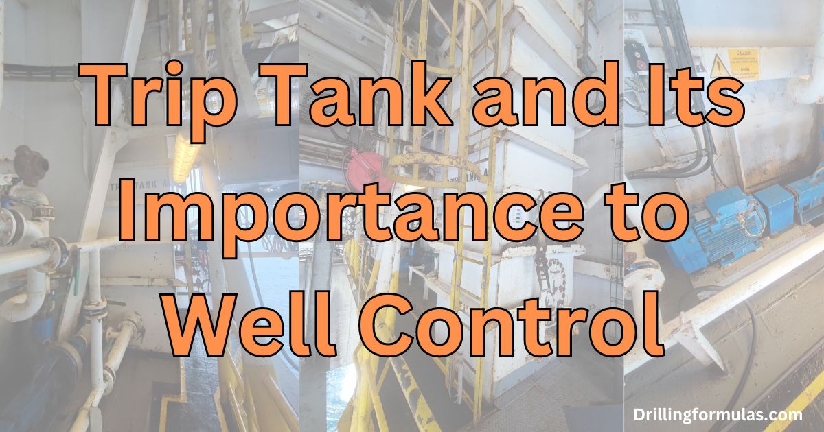
The diagram (Figure 1) below demonstrates how the trip tank is lined up.

Figure 1 – Trip Tank Line Up To Continuously Fill The Hole