Dilution of Mud System to Control Low Gravity Solid

By adding bbl of base fluid required, dilution of mud can help control Low Gravity Solid (LGS) in mud system. This post will demonstrate you how to determine barrels of dilution fluid such as water or base fluid required to achieve the desired low gravity solid.

Formula used to calculate dilution of mud system is listed below;

Vwm = Vm x (Fct – Fcop) ÷ (Fcop)

Where; Vwm = barrels of dilution water or base fluid needed

Vm = total barrels of mud in circulating system

Fct = percent low gravity solids in system

Fcop = percent total low gravity solids desired

Example: Determine how much barrels of base oil to dilute total 2000 bbl of mud in system from total LGS = 7 % to desired LGS of 3.5 %.

Vm = 2000 bbl

Fct = 7%

Fcop = 3.5%

Vwm = 2000 x (7 – 3.5) ÷ 3.5

Vwm = 2000 bbl

In order to dilute total of 2000 bbl of the original mud with 7% LGS down to 3.5% LGS, 2000 bbl of base oil is required to add into the system.

Please find the excel sheet used to calculate how much barrel of base fluid to control Low Gravity Solid (LGS) in mud system.


Ref book: Formulas and Calculations for Drilling, Production and Workover, Second Edition

How to Assess Material Requirements for Drilling Operation

Drilling supervisors must be responsible for assessing material requirements for the drilling operation at a drilling rig. There are several following information that can help to assess material requirement in both short time (less than 48 hrs) and long time (next 3-5 day).

1. Drilling Operation Instruction: The drilling operation instruction is guidance for what operations will be happening in the future. Therefore, it will give people at the rig some ideas regarding what people will be needed.

2. Drilling Operation Meeting: The operation meeting is conducted everyday in order to discuss the forward plan among team members such as drilling supervisors, a drilling contractor and service companies. This meeting helps all parties at the rig to understand what drilling activities will be performed and when the operation requires the material perform jobs.

3. Forward plan sheet: The forward plan sheet contains all actions from demobilization to completion of the drilling program. It assists supervisors on the rig to estimate time for upcoming operations. Mostly, it is utilized for assessing the long time (next 3-5 days) material and people requirement.

4. Area on the rig: Operation supervisors must fully understand about available space of the rig because it is a constraint about how much equipment can be store on the rig. For instant, if the rig has small area, small set of equipment must be frequently ordered. On the other hand, if the rig area is big, a lot of drilling tools can be requested and kept on the rig.

5. Logistics: It is very important to know how the logistics work each area because it will help personnel on the rig know how long the equipment will be transferred from a wear house to a location after issuing the material.

6. Contact Warehouse: After all required materials are assessed, drilling supervisors and a material man must contact a warehouse in order to discuss with them about what the required materials are and when they should be at the rig site.

Normally, material requirement plan must be revised everyday because sometimes drilling operation is not ongoing as plan. Therefore, some equipment must be delayed or some special equipment must be urgently requested for specific drilling operation.

Oil Field Abbreviation Mostly Used in the Rig

This is may not relate to drilling formula but it may be good for new people to know about oil field abbreviations. If you have more than what I have, please feel free to add more by putting in the blog comment.

ACF – Annular Capacity Factor

AV – Annular Velocity

BF – Buoyancy Factor

BHA – Bottom Hole Assembly

BHP – Bottom Hole Pressure

BOP – Blow Out Preventor

BOPE – Blow Out Preventer Equipment

BPUTS – Bring Pumps Up To Speed

CC – Circulate and Condition mud

CLF – Choke Line Friction

CMW – Current Mud Weight

CP – Casing Pressure

DC – Drill Collar

Dh – Diameter of hole in inches

DP – Drill Pipe

DPP – Drill Pipe Pressure

ECD – Equivilant Circulating Density

EOB – End of Build

ESP – Estimated Stuck Point or Electical Submersible Pump

FCP – Final Circulating Pressure

FD – Fluid Density

FIT – formation integrity test

FOSV – Full Opening Safety Valve

FP – Formation Pressure

FrP – Friction Pressure

FV – Funnel Viscosity

GPM – Gallons Per Minute

HHP – Hydraulic Horse Power

HP – Hydrostatic Pressure

IBOP – Inside Blow Out Preventer

ICP – Initial Circulating Pressure

ISICP – Initial Shut-in Casing Pressure

KLF – Kill Line Friction

KMW – Kill Mud Weight

KOP – Kick Off Point

Lbs. – Pounds

LC – Lost Circulation

LCM – Lost Circulation Material

Len – Length in feet

LOT – Leak Off Test

MAASP – Maximum Allowable Annular Surface Pressure

MASP – Maximum Anticipated Surface Pressure

MD – Measured Depth

MGS – Mud Gas Separator

MI – Mud Increment

MISICP – Maximum Initial Shut-in Casing Pressure

MOP – Margin of Over Pull

MW – Mud Weight in ppg

NP – Neutral Point

OBM – Oil Based Mud

OMW – Original Mud Weight

OPT – Optimum

PG – Pressure Gradient

PI – Pressure Increment

POH – Pull Out Hole

PP – Pore Pressure

PPG – Pounds Per Gallon

RIH – Run In Hole

ROH – Run Out Of Hole

RPM – Rounds Per Minute

RSS- Rotary Steerible System

SCR – Slow Circulating Rate

SG – Specific Gravity

SICP – Shut-in Casing Pressure

SIDPP – Shut-in Drill Pipe Pressure

SOBM – Synthetic Oil Based Mud

SP – Surface Pressure

SPM – Strokes Per Minute

SPM Valve – Side Pocket Mandrel Valve

SPR – Slow Pump Rate

TDS – Top Drive System

TIH – Trip In Hole

TOC – Top Of Cement

TOF – Top Of Fish

TOH or TOOH – Trip Out Of Hole

TOL – Top Of Liner

TVD – True Vertical Depth

WL – Water Loss or Wire Line

WOB – Weight On Bit

WOC – Wait On Cement

WOO – Wait On Orders

WOW – Wait On Weather

YP – Yield Point

Weight of slug required for desired length of dry pipe with set volume of slug

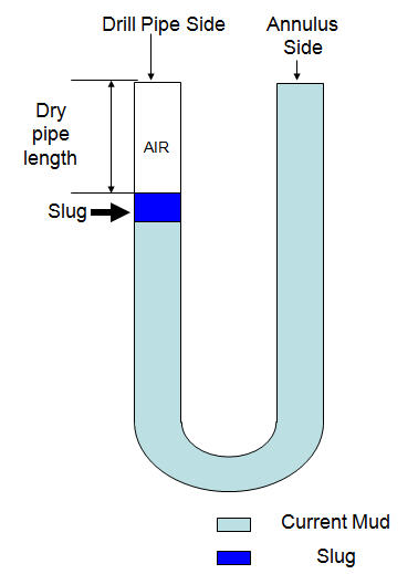
You can determine how much slug weight required in order to achieve desired length of dry pipe with certain slug volume that you will use.

slug lenght dry pipe

Oilfield Unit

Please follow these steps of calculation below;

Step 1 Determine Length of slug in drill pipe in ft:

Length of slug in drill pipe in ft = slug volume in bbl ÷ drill pipe capacity in bbl/ft

Step 2 Determine hydrostatic pressure required to give desired dry pipe drill pipe:

Hydrostatic Pressure in psi = mud weight in ppg × 0.052 × desired length of dry pipe

Step 3 Determine slug weight needed in ppg:

Slug weight in ppg = (Hydrostatic Prำssure (from step 2) ÷ 0.052 ÷ Length of slug in ft (step1)) + mud weight, ppg, in hole

Example: Determine slug weight required for the following data:

Desired length of dry pipe = 200 ft

Mud weight in hole = 12.0 ppg

Drill pipe capacity = 0.016 bbl/ft

Volume of slug = 20 bbl

Step 1 – Determine Length of slug inside drill pipe in ft:

Slug length = 20 bbl ÷ 0.016 bbl/ft

Slug length = 1250 ft

Step 2 – Determine hydrostatic pressure required to give desired dry pipe drill pipe

Hydrostatic Pressure in psi = 12.0 × 0.052 × 200

Hydrostatic Pressure in psi = 124.8 psi

Step 3 – Determine slug weight needed in ppg:

Slug weight in ppg = (124.8 ÷ 0.052 ÷ 1250) + 12.0

Slug weight in ppg = 13.9 ppg

Metric Unit

Please follow these steps of calculation below;

Step 1 Determine Length of slug in drill pipe in meter (m):

Length of slug in drill pipe in m = slug volume in m³ ÷ drill pipe capacity in m³/m

Step 2 Determine hydrostatic pressure required to give desired dry pipe drill pipe:

Hydrostatic Pressure in psi = mud weight in kg/m³ × 0.00981 × desired length of dry pipe in m

Step 3 Determine slug weight needed in ppg:

Slug weight in ppg = (Hydrostatic Pressure (from step 2) ÷ 0.00981÷ Length of slug in m (step1)) + mud weight, kg/m³, in hole

Example: Determine slug weight required for the following data:

Desired length of dry pipe = 120 m

Mud weight in hole = 1,400 kg/m³

Drill pipe capacity = 0.007824 m³/m

Volume of slug = 4.5 m³

Step 1 – Determine Length of slug inside drill pipe in ft:

Slug length = 4.5 m³÷ 0.007824 m³/m

Slug length = 575 m

Step 2 – Determine hydrostatic pressure required to give desired dry pipe drill pipe

Hydrostatic Pressure in psi = 1,400 × 0.00981 × 120

Hydrostatic Pressure in psi = 1,648 KPa

Step 3 – Determine slug weight needed in ppg:

Slug weight in ppg = (1,648 ÷ 0.00981 ÷ 575) + 1,400

Slug weight in ppg = 1692 kg/m³

Please find the excel sheet used to calculate Weight of slug required for a desired length of dry pipe with a set volume of slug.

Ref books: 

Lapeyrouse, N.J., 2002. Formulas and calculations for drilling, production and workover, Boston: Gulf Professional publishing.

Bourgoyne, A.J.T., Chenevert , M.E. & Millheim, K.K., 1986. SPE Textbook Series, Volume 2: Applied Drilling Engineering, Society of Petroleum Engineers.

Mitchell, R.F., Miska, S. & Aadny, B.S., 2011. Fundamentals of drilling engineering, Richardson, TX: Society of Petroleum Engineers.