Suction Anchor Calculation

Suction anchor or suction caisson is an offshore foundation which is quite popular for offshore installation. It utilizes a negative pressure concept to drive the suction anchors down. This article will demonstrate some simple calculations used for the suction anchor.


Example:

A suction anchor, 40” OD x36” ID, is deployed as part of a mooring anchor for a floating production platform in 900 ft of water. The initial penetration due to its weight is 5 feet into the sea.  Soil resistance is 450 lb/ft2 by average.  Based on the given information, determine values from these two questions below;

  • What is the volume evacuated for each foot of penetration?
  • How long of a suction anchor will be needed so that the top of the suction anchor is 5 ft above the seabed at the end of the operation?
Figure 2 - Suction Anchor Submerse by Its Weight

Figure 2 – Suction Anchor Submerse by Its Weight

Important Information

The sea water density = 64.0 lb/cu-ft (8.6 ppg)

Steel specific gravity = 785

What is the volume evacuated for each foot of penetration?

Assumption: Impermeable formation
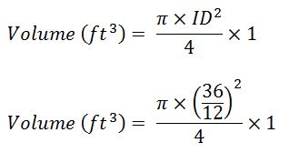
vol1

Volume (ft3) = 7.07

How long of a suction anchor will be needed so that the top of the suction anchor is 5 ft above the seabed at the end of the operation?

Figure 3 – Suction Anchor Diagram (Before and After)

Figure 3 – Suction Anchor Diagram (Before and After)

The initial penetration support weight of the suction anchor therefore is only the frictional force between soil at the seabed and the hydrostatic pressure from the water column will be taken into account.

L = the length of the suction anchor resisting the force from hydrostatic pressure applied at the top of the suction anchor.

This is assumed that the friction generated by initial penetration continues to oppose and equal the buoyed weight of the suction anchor.

Based on the assumption, the force from soil resistance is equal to force from the hydrostatic pressure acting against the top of the suction anchor.

450 × surface area = Hydrostatic pressure × area of top of the suction anchor

cal

L = 56.2 ft

Total length of the suction anchor = 5+ 56.2 + 5 = 66.2 ft

Figure 4 demonstrate the final condition compared to the initial condition.

Final Diagram

Final Diagram

References

James G. Speight, 2014. Handbook of Offshore Oil and Gas Operations. 1 Edition. Gulf Professional Publishing.

Trond Bendiksen, 2015. Commissioning of Offshore Oil and Gas Projects: The manager’s handbook. Edition. AuthorHouse.

Joseph A. Pratt, 1997. Offshore Pioneers: Brown & Root and the History of Offshore Oil and Gas. Edition. Gulf Professional Publishing.

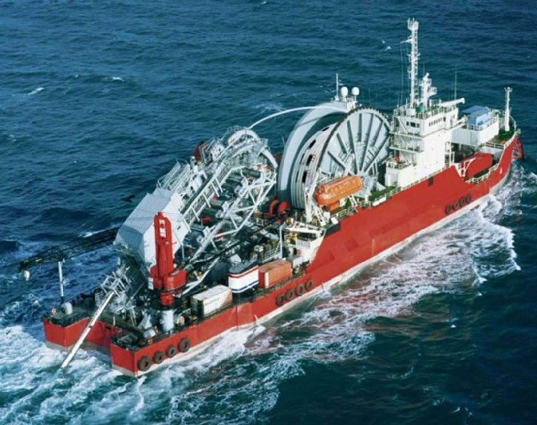
SEMAR AS, (2013), Shelley Field [ONLINE]. Available at: http://www.semar.no/semar/bilder/Shelley-field.jpg [Accessed 29 July 2016].

Pipeline Towing Method for Pipeline Installation

Pipeline towing method is useful for bundled pipelines where several pipelines with different functions are packed together inside a large carrier pipe. The pipeline is constructed in a designed length onshore and towed into the sea.

Figure 1 – Bundled Pipeline Ref: https://anthropologyinthewind.files.wordpress.com

Since there are many pipelines bundled together inside a big carrier pipe, it is imperative to get everything right prior to installation.  Due to this reason, this installation technique allows the bundled pipeline to be welded, inspected and tested onshore prior to installation in order to minimize failure.

Four categories for the pipeline towing method are as follows; Continue reading

You Can Travel To North Sea’s Oil Platform as Tourists

You can imagine that you can travel to the Troll A platform in the North Sea without working in the oil and gas industry.  It cost you quite a lot of money 🙂

This is the news below.

Bored with palm-fringed beaches and turquoise seas? Then the gigantic oil platforms of the North Sea beckon. The first ever “rig-spotting” cruise just ended off the coast of Norway, and those onboard the four-day trip said it was jawdropping.

“I couldn’t believe that these big buildings could be made,” said passenger Kari Somme, 86, after seeing Statoil’s (STL.OL) Troll A platform – the heaviest structure ever moved by mankind – towering 200 meters (650 feet) above the surface of the sea.

Continue reading

Reel Lay Pipeline Installation Method

Reel lay method installs offshore pipeline by sending the pipeline from a reel mounted on a special pipeline installation vessel. Instead of connecting each joint of pipe line at an offshore location like other methods (S-lay and J-lay method), the pipeline is pre-assembled in a spool which is mounted on the deck of the reel barge. This method can lay pipe up to 16” diameter and water depth capacity for 16” pipeline is about 800 m (2,600 ft). This method cannot lay such a big size pipe because the big pipeline is not flexible enough to be rolled into a reel.

The reels can be installed either horizontal or vertical. Horizontal reel barges can do only S-lay installation; however, vertical reel barges can perform both J-lay and S-lay pipeline installation.

The reel lay method is considered to be the fastest laying method because the majority of welding and inspections are performed onshore in order to minimize time for installation. Once all pipe on the reel is laid, the barge either head back to shore of another reel or lift a new reel from a supply boat. This is dependent of each vessel.

Some of the images of reel lay barges are shown below;

Figure 1 – Vertical reel-lay barge in S-lay configuration

Continue reading