The friction pressure is pressure loss when fluid flowing through flowing paths and it acts in the opposite direction of fluid flow.
The following factors affect the friction pressure:
• Drilling string geometry both inside diameter and outside diameter
• Fluid Properties: Rheology and density
• Geometry of wellbore: hole length, wellbore area and flow area
• Wellbore condition such as packing off, bridging, etc
• Flow Rate
• Pipe movement and pipe rotation
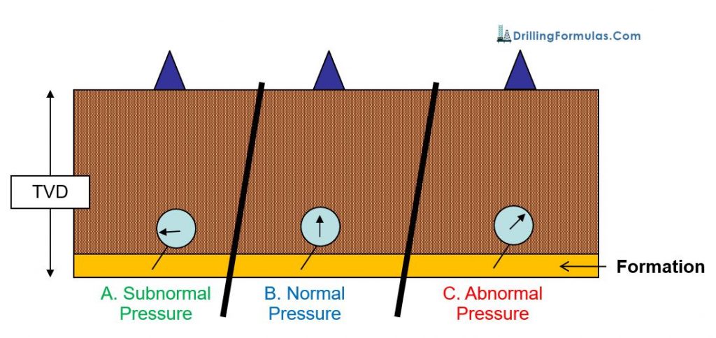
Let’s illustrate friction pressure
- Pump fluid with pressure upstream of 2,000 psi and discharge at atmosphere (0 psi)
- Pressure gauge in the middle reads 1,000 psi
- The diagram is shown in Figure 1.
- Pressure acts in the opposite direction of flow.
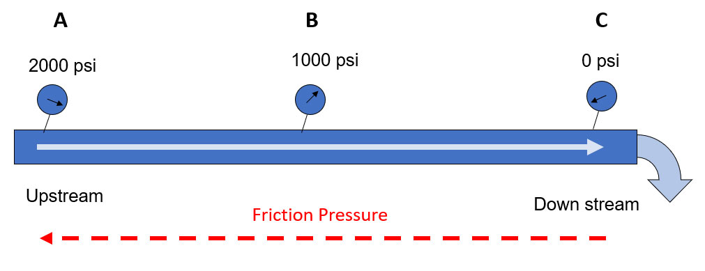
Figure 1 – Simple diagram of fluid flow and friction pressure
- Friction pressure between A and B is equal to P at A – P at B. Therefore, friction pressure between A and B is 1000 psi as shown in Figure 2.
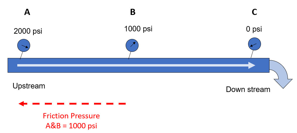
Figure 2 – Friction pressure between A and B
- Friction pressure between B and C is equal to P at B – P at C. Therefore, friction pressure between B and C is 1000 psi as shown in Figure 3.
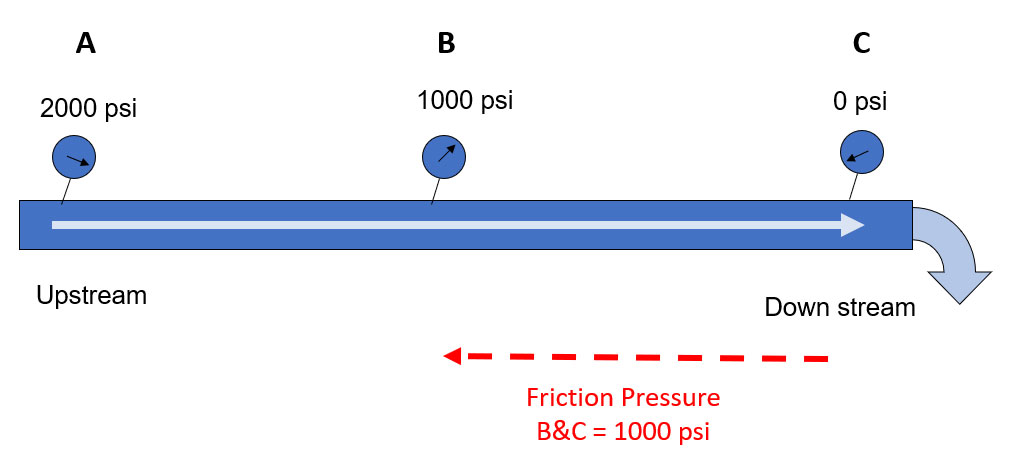
Figure 3 – Friction pressure between B and C
- Total pressure loss of this system (Friction Pressure) is 2000 psi (Figure 4).
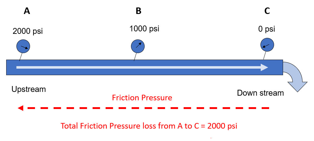
Figure 4 – Total friction pressure between A and C
Friction in a wellbore
We will apply this concept to our wellbore. This is a well with a normal forward circulation from drillstring and come out on surface from the annulus. These are some information.
- Constant Fluid both sides
- Hydrostatic Pressure = 2,500 psi
- Friction P in Drillpipe = 1,500 psi
- Friction P in Annulus = 500 psi
The well diagram is show in Figure 5.
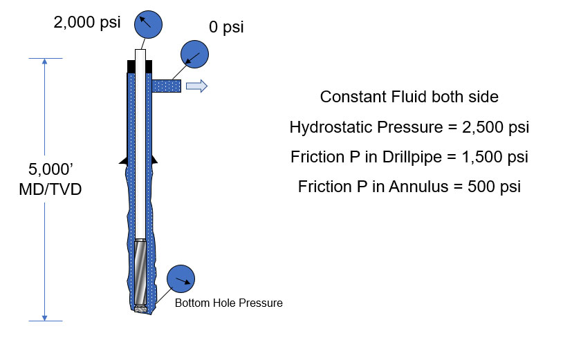
Figure 5 – Wellbore Diagram
We can draw a simple diagram by applying U-tube concept as shown in Figure 6.

Figure 6 – Well Diagram applied U-Tube concept
Figure 7 shows the relationship in the drill pipe side.
DP – FrPdp + HPdp = BHP
Where;
DP = Drillpipe Pressure
FrPdp = Friction pressure at drillpipe side
HPdp = Hydrostatic pressure at drillpipe side
BHP = Bottom hole pressure
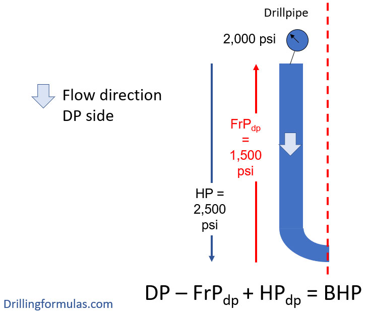
Figure 7 – Relationship on Drillpipe Side
Figure 8 shows the relationship in the casing side.
BHP =CP + FrPann +HPann
Where;
CP = Casing Pressure
FrPann = Friction pressure in annulus
HHPann = Hydrostatic pressure in annulus
BHP = Bottom hole pressure
** You will see that in the annulus friction pressure will act to the bottom hole since the flow moves upward direction so the sign is +.
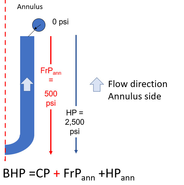
Figure 8 – Relationship on Casing Side
Figure 9 demonstrates the whole relationship of the whole system.
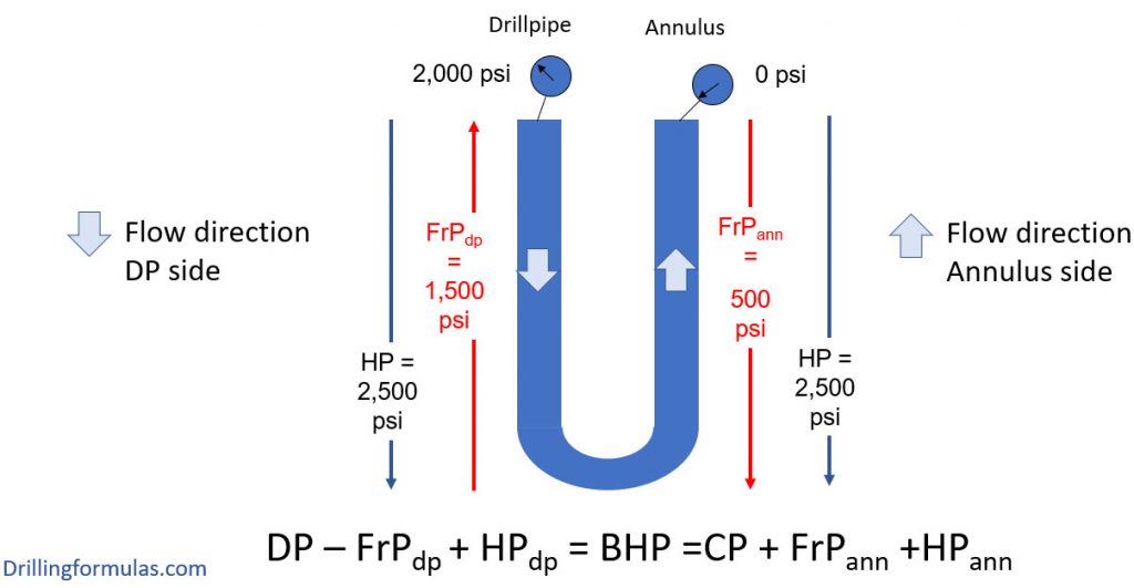
Figure 9 – Relationship of the whole system
Let’s do some calculation to get more understanding about this topic based on this example.
Starting from the drillpipe side (Figure 10),
DP – FrPdp + HPdp = BHP
2,000 – 1,500 + 2,500 = BHP
BHP = 3,000 psi
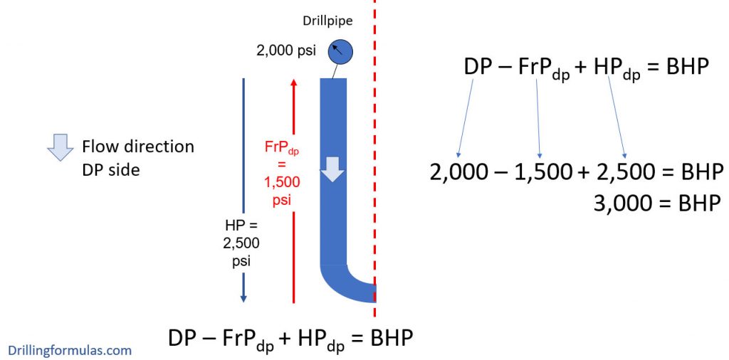
Figure 10 – Calcification from the drill pipe side
Calculation from annulus side (Figure 11)
BHP =CP + FrPann +HPann
BHP =0 + 500 +2,500
BHP = 3,000 psi
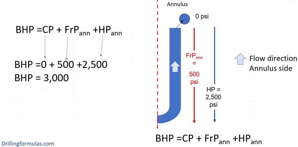
Figure 11 – Calculation from the annulus side
Figure 11 demonstrates the whole system. As you can see that we can calculate the BHP from any side and we will get the same result as per U-Tube principle.
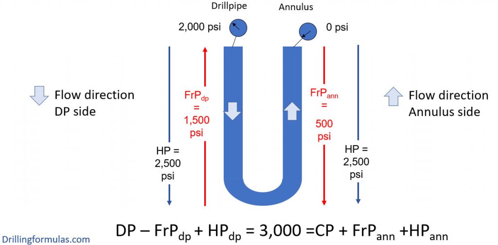
Figure 12 – Whole system calculation
With this example, we wish that would make you get more understanding about friction pressure in a wellbore.
Please leave any comments or questions below if you have any questions.
References
Cormack, D. (2007). An introduction to well control calculations for drilling operations. 1st ed. Texas: Springer.
Crumpton, H. (2010). Well Control for Completions and Interventions. 1st ed. Texas: Gulf Publishing.
Grace, R. (2003). Blowout and well control handbook [recurso electrónico]. 1st ed. Paises Bajos: Gulf Professional Pub.
Grace, R. and Cudd, B. (1994). Advanced blowout & well control. 1st ed. Houston: Gulf Publishing Company.
Watson, D., Brittenham, T. and Moore, P. (2003). Advanced well control. 1st ed. Richardson, Tex.: Society of Petroleum Engineers.