Benefits of Casing while Drilling

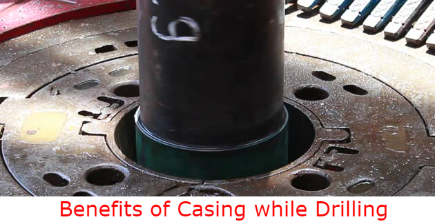
Casing while drilling provides immediate benefits, saving both time and money by altering the steps needed for the drilling process. On top of this, the CwD system also provides a whole host of additional benefits. The benefits of casing while drilling can be summarized below;

benefits-of-casing-while-drilling-cover

Save Time and Cost

As mentioned in the introduction part, Basic Knowledge of Casing while Drilling (CwD), CwD is able to save operation time by cutting down flat time and reducing operational risk. When compared to conventional drilling, CwD can provide a time saving of between up to 37.5% of time spent on a well based on historical data from a field in Oman (136107-PA SPE Journal Paper – 2012). Continue reading

Basic Knowledge of Casing while Drilling (CwD)

Casing while drilling (CwD) has been around for many years and it is one of proven technologies that can save both time and money. CwD is a process where a well is simultaneously drilled and cased; the casing is used for the drill string, and is rotated to the drill and cemented into the well at TD. One of the main benefits of this process is that it greatly cuts down on the tripping time needed to pull out the bottom hole assembly (BHA) and run the case- if not removing this need entirely. Therefore, the flat time is reduced, and the process is made more economically viable.

Figure 1- Casing while Drilling Operation (Courtesy of Weatherford)

Figure 1- Casing while Drilling Operation (Courtesy of Weatherford)

As shown in Figure 2 below, which is an example of Casing while Drilling utilized in one of oilfields in Oman for drilling surface section; this process can save up to 37.5% of time spent on a well based on historical data.

Figure 2 – A comparison between conventional drilling and casing while drilling of one field in Oman (136107-PA SPE Journal Paper - 2012).

Figure 2 – A comparison between conventional drilling and casing while drilling of one field in Oman (SPE 136107-PA ,SPE Journal Paper – 2012).

Continue reading

Well in an Unbalanced Condition (Video)

The well is in an underbalanced condition while pulling out of hole. You can see in the video below that the fluid is flowing up from the drill pipe side. It is such very important to understand the condition of the well and have the plan to deal with it.


These are some thought about this situation from our member in the Facebook fanpage.

Hossam Hamza – Looks like it was failed balanced cement plug job, I see long cement chiksan line on rig floor and circulating head connected with low TQ valve above 1 joint DP in mouse hole, the back flow due to over displacement. Is my guess right???? Continue reading

Magnetic Declination and Grid Convergent and Their Applications in Directional Drilling

This article will describe about Magnetic Declination and Grid Convergent and how to use them for directional drilling purposes.

Magnetic Declination

In the azimuth reference, three North references are Magnetic North, True North and Grid North (Figure 1). Since these 3 North references are not the same direction; therefore, it must be a correction in order to convert any Azimuth in the same reference. Two main concepts, which are magnetic declination and grid convergent, are used to AZI from the magnetic tool to the AZI referencing to the Grid North.

Figure 1 - True North, Magnetic North and Grid North

Figure 1 – True North, Magnetic North and Grid North

Continue reading

Latitude, Longitude and Drilling Map Projection

Directional drilling maps are flat, but the Earth is an oblate spheroid. This leads to a challenge to accurately represent the wellbore position on the Earth on a piece of paper. In this section, you will learn about mapping techniques used in directional drilling, limitations and the errors of mapping techniques.

One of the most important concepts of mapping is latitude and longitude.

Latitude is a coordinate used to specify the north-south position of a location on the surface of the Earth. Latitude is an angle which starts from 0° at the equator to 90° at the Earth North-South poles. It is simply defined like this;

  • 0 ° at the equator
  • +90 ° at the North pole
  • -90 ° at the South pole

To define latitude, it is described in degrees, minutes and seconds. Parallel line of latitude is a small circle at particular latitude which is parallel with the Equator.

Figure 1 - Latitude and Longitude Diagram

Figure 1 – Latitude and Longitude Diagram

Continue reading