Geologists have known for years that substantial deposits of oil and natural gas are trapped in deep shale formations. These shale reservoirs were created tens of millions of years ago. Around the world today with modern and horizontal drilling techniques and hydraulic fracturing, the trapped oil and natural gas in these shale reservoirs is being safely and efficiently produced, gathered and distributed to customers.
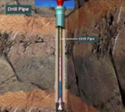
Let’s look at a drilling and completion process of a typical oil and natural gas well. Shale reservoirs are usually one mile or more below the surface. Well below any underground source of drinking water, which is typically no more than 300-1000 feet below the surface(Figure 1)
This is another training VDO that is very good for entry level personnel who are working in the oilfield industry especially drilling part. This VDO will give the over view regarding rig types and their applications.
Additionally, we also add the VDO transcript to help people understand about the content clearly. Please feel free to share if you think this is advantageous for anybody.
We are always looking for more sources of natural gas and the best way to find natural gas currently is b looking in shale deposits. We are doing this with a process called hydraulic fracturing or “fracking” as it is more commonly known as. There’s great controversy in this practice as well as great potential to reach larger deposits of natural gas which can then be used as fuel.
Going Forward with Shale Gas
Currently shale gas is a popular way to get natural gas out of the ground but this may be stalled as more environmental groups oppose the fracking methods as they feel it harms the environment in the process. The biggest threat to the production of of shale gas environmental concerns which are only going to continue as more people oppose this method of natural gas production in many areas of the world.
This is a great VDO Training about drill string components. We also added the detailed transcripts so you can learn from the VDO effectively.
Please give us comments if you think this is useful for you.
Transcription of Drill String Components
There are many components that make up the drill string as shown in this graphic. Drill pipe is a strong but relatively lightweight pipe. Crew members attach it to a top drive or Kelly. Drill pipe forms the upper part of the drill string. Usually the drill pipe rotates which also rotates the bit. Each section of pipe is called a joint. Crew members screw together or make up several joints and put them in to the hole as the bit drills.
Positive displacements pumps are generally used on drilling rigs to pump high pressure and high volume of drilling fluids throughout a drilling system. There are several reasons why the positive displacement mud pumps are used on the rigs.
• The pumps can work with fluids with high solid content.
• There are wide ranges for pressure and flow rate.
• They are more reliable and able to pump at tough conditions.
• They are easy to operate and maintain.
Duplex and Triplex pumps are positive displacement pumps which are commonly used in the oilfield.
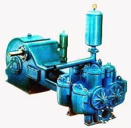
Duplex Pumps – 2 cylinders, double acting
Figure 1 – Duplex Pump
The duplex pumps (Figure 1) have two cylinders with double acting. It means that pistons move back and take in drilling mud through open intake valve and other sides of the same pistons, the pistons push mud out through the discharge valves.
The following diagrams demonstrate how duplex mud pumps work.
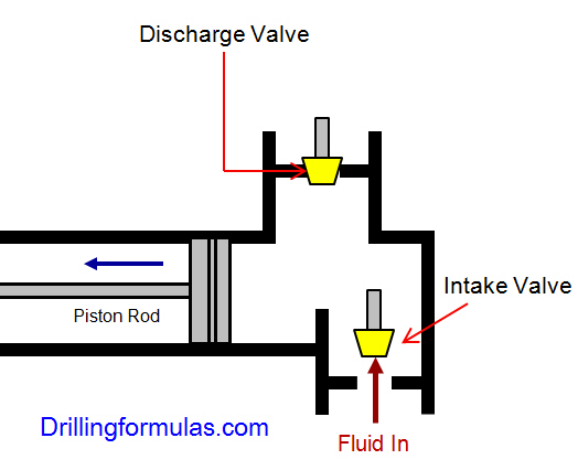
Figure 2 – Position of Piston Rod and Fluid Movement of Duplex Pump
When the piston rod is moved forward, one of intake valves is lift to allow fluid to come in and one of the discharge valve is pushed up therefore the drilling mud is pumped out of the pump (Figure 2).
Figure 3 -Position of Piston Rod and Fluid Movement of Duplex Pump
On the other hand, when the piston rod is moved backward drilling fluid is still pumped. The other intake and discharge valve will be opened (Figure 3).
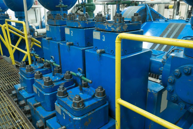
Triplex Pumps – 3 cylinders, single acting
The triplex pumps have three cylinders with single acting. The pistons are moved back and pull in drilling mud through open intake valves. When the pistons are moved forward and the drilling fluid is pushed out through open discharge valves.
Figure 4 Triplex Pump
The following diagrams demonstrate how the triplex mud pumps work.
Each diagram shows the action of one cylinder.
Figure 5 – Position of Piston Rod and Fluid Movement of Triplex Pump (Discharge)
When the piston rods are moved forward, the intake valves are in close position and the discharge valves are in open position allowing fluid to discharge (Figure 5).
Figure 6 Position of Piston Rod and Fluid Movement of Triplex Pump (Suction)
On the contrary when the piston rods are moved backward, the intake valve are opened allowing drilling fluid coming into the pump (Figure 6). This video below shows how a triplex mud pump works.
Which one is the most practical mud pump on the rig nowadays?
Triplex pumps are more popular than duplex pumps because of being lighter, smoother discharge and lower maintenance cost.
Calculations Related to Positive Displacement Mud Pumps
Hydraulic Horse Power (HPP) formula is listed blow
HHP= (P x Q) ÷1714
Where;
HHP = hydraulic horsepower
P = circulating pressure, psi
Q = circulating rate, gpm
Because each pump has power rating limit as 1600 hp, this will limit capability of pump. It means that you cannot pump at high rate and high pressure over what the pump can do. Use of a small liner will increase discharge pressure however the flow rate is reduces. Conversely, if a bigger liner is used to deliver more flow rate, maximum pump pressure will decrease.
The figure 7 below shows the performance of mud pump National 12-P-160 TRIPLEX MUD PUMP.
Figure 7 – Pump Performance Chart
As you can see, you can have 7500 psi with 4.5” liner but the maximum flow rate is only 297 GPM. If the biggest size of liner (7.25”) is used, the pump pressure is only 3200 psi.
Triplex Pump Output Formula
Triplex Pump Output in bbl/stk = 0.000243 × (liner diameter in inch) 2 ×(stroke length in inch)
Duplex Pump Output Formula
Duplex Pump Output in bbl/stk = 0.000162 × S × [2(D)2 – d2]
Where:
D = liner diameter in inch
S = stroke length in inch
d = rod diameter in inch
These formulas are based on 100% efficiency.
The actual pump output must be considered pump efficiency.
Finally, we hope that this article would give you more understanding about the general idea of drilling mud pumps. Please feel free to add more comments.